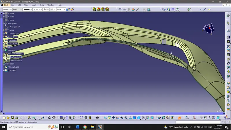
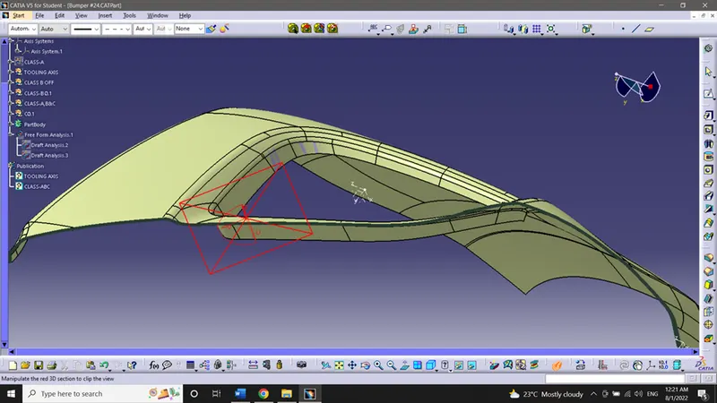
Week 8 - Challenge 4 - Bumper
DRAFTING ANALYSIS
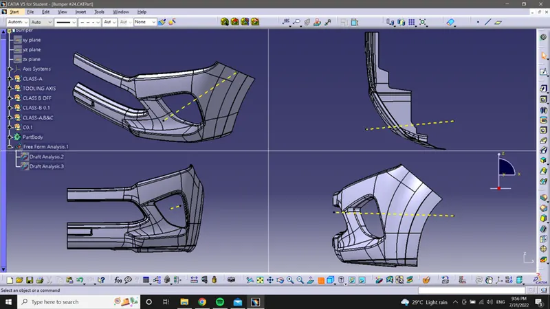
Tooling axis
- Here I took my tooling axis position about the centre of headlight hole.
- So I have made a point about the centre of the hole, and insert an axis system on that point.
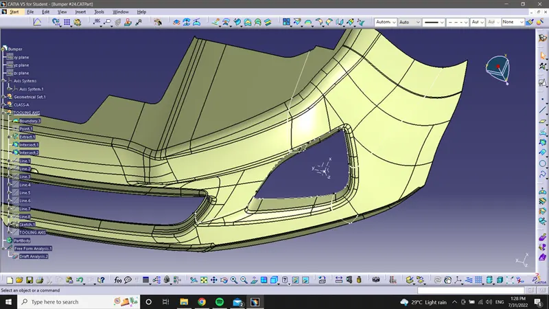
- made intersect on the class-A surafce with reference to the XZ and YZ-planes, from that profile created four lines.
Bisecting Method
- Using bisect line type created one line throgh the point reference to XZ-plane, similarly On the YZ-plane.
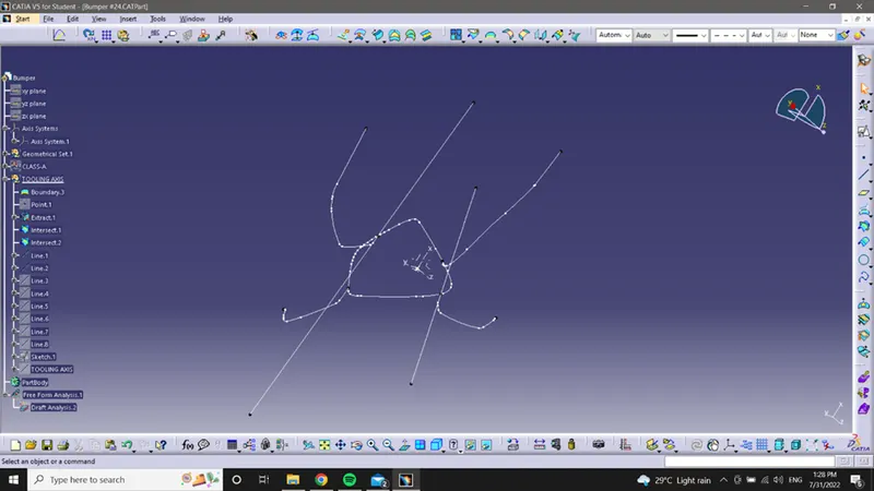
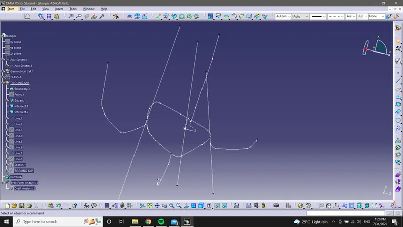
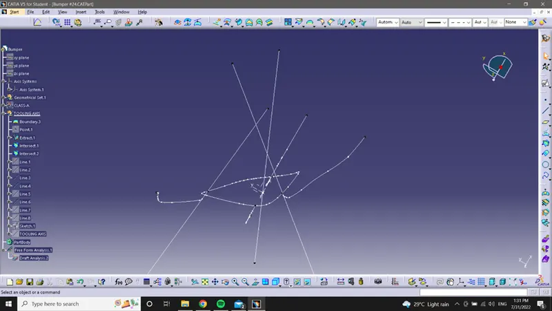
- Using the 2 new lines, made another line using bisect line method.
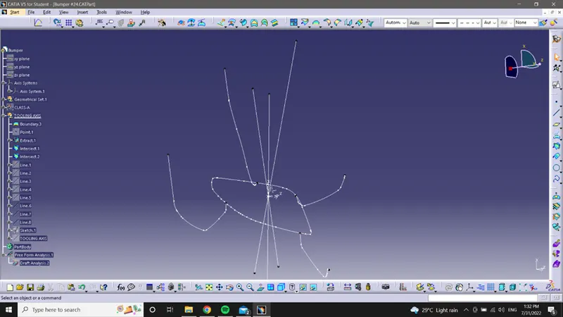
- Then created a sketch on the XZ-plane, made a line in the sketch throgh the origin making an with the line created throgh the profile of the big wall of bumper.
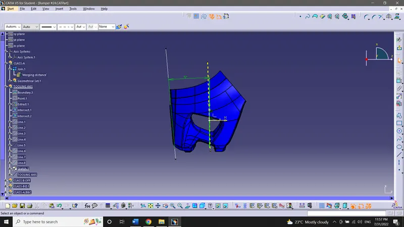
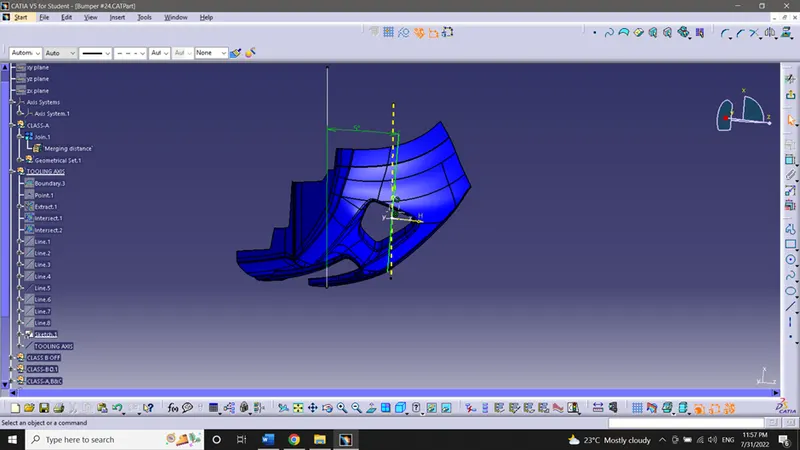
- Using the recently created line in the sketch and the line created using the bisect method at last, made our tooling axis using bisecting line method.
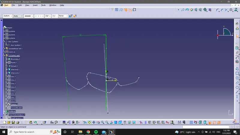
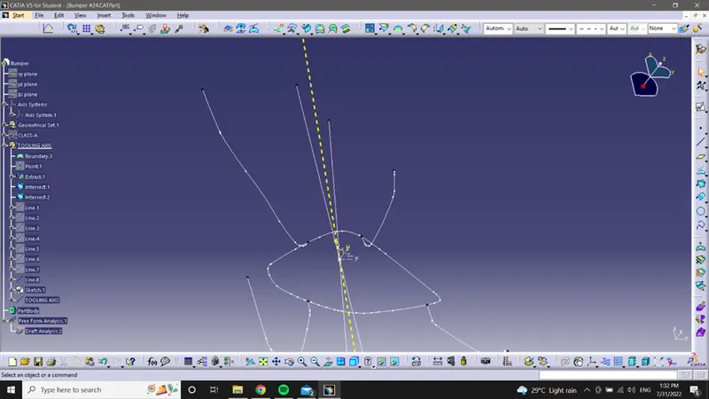
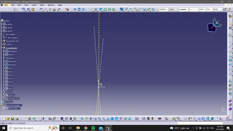
- The thickened yellow line is our tooling axis.
Drafting analysis on the Class-A Surface
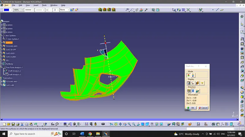
- Green color indicated drafting angle greater than 3 degree.
- Blue color indicates drafting angle less than three and greater than zero.
- Similarly Red color indicated angle less than zero or negetive angles.
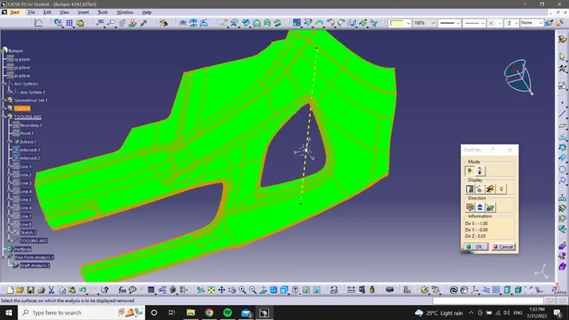
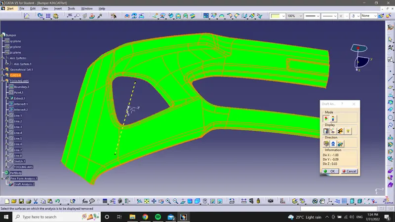
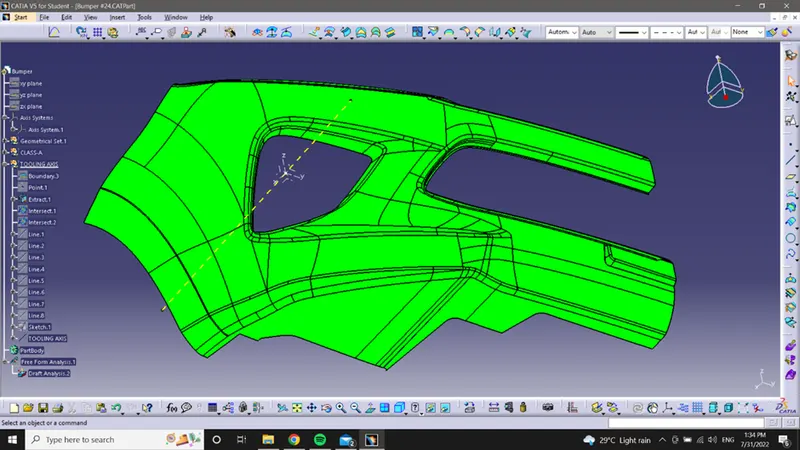
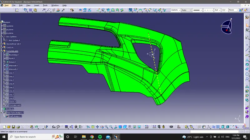
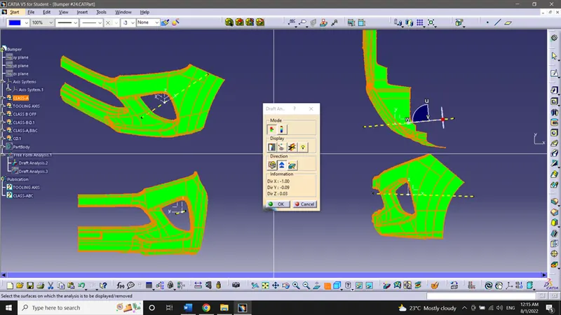
Drafting Analysis of the solid body (plastic component)
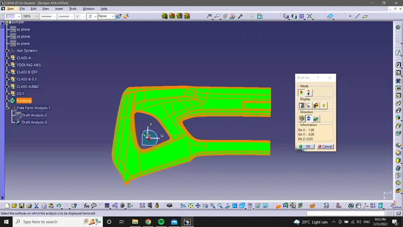
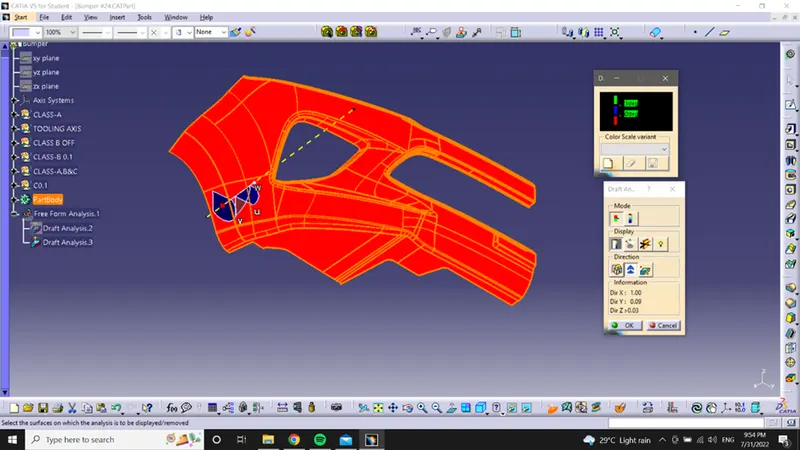
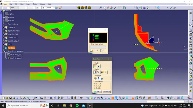
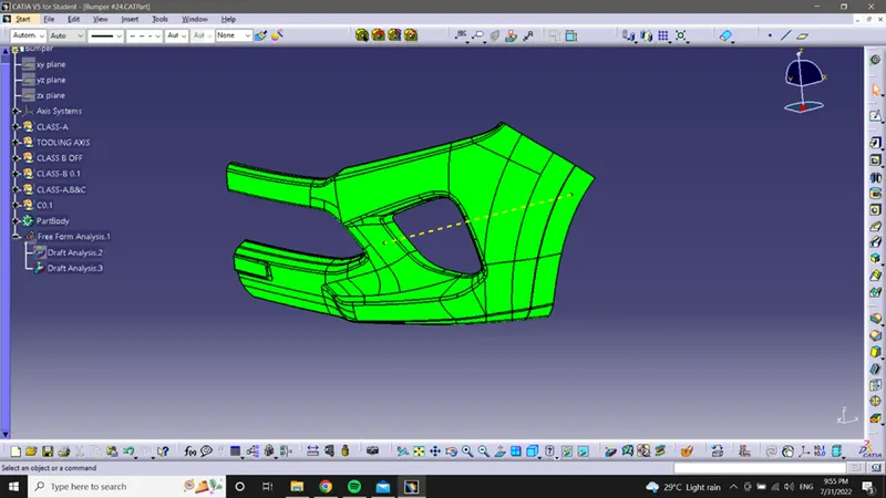
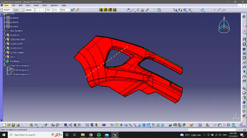
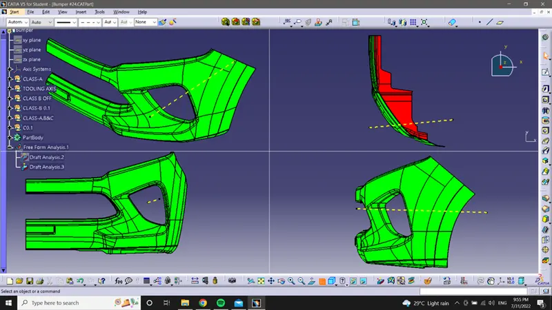
Different Views of the solid body
surface integrated
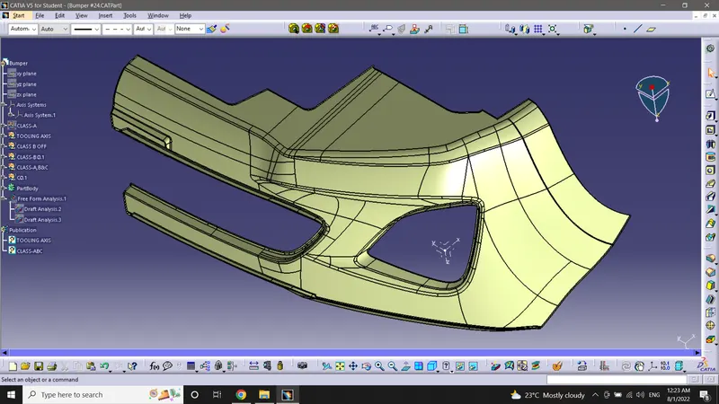
Sectional view with surface and solid body