Week 8 - Challenge 4 - Bumper
REPORT :
1. First insert a point on the surface of the class A by extracting the base
2. The selected surface is in such a way that the majority portion of the object have to be cleared and the remaining portion is in such a way that it can be cleared in the tooling direction.
3.The bisecting line can be obtained by the combination of two lines that are extracted from the walls or surfaces of the object
4.Draft analysis can be performed by selecting the 3D axis drag it near to the main tooling axis and place it and then need to click the compass option it will automatically adjusted,thus draft analysis is performed.
Draft Analysis :
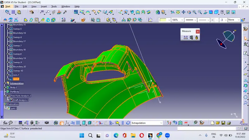
1.Green color indicates that the degree is from 0 to 3 degrees
2.Red color indicates that the degree is from 0 to 2.9 Degrees
3.Blue color indicates that the degree is from 0 to negative
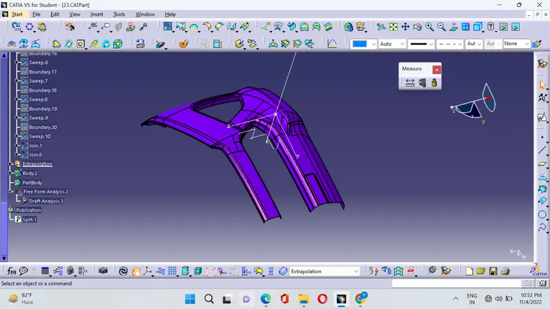
Class A :The surface is defined has the object that we can see with our eyes and it is said to be the aesthetic surface,this surface should be smooth and free from defects and the surface should be smooth
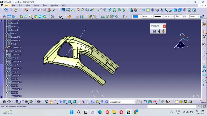
Class B : This surface is defined has the surface parallel to the class A or it is said to be the engineering surface where all the engineering features takes place.
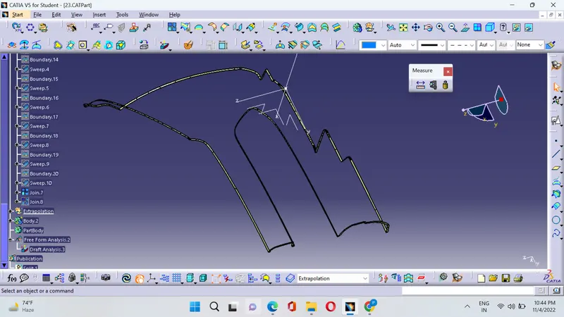
Class C : This surface is defined has the surface that joins both the class A and C .
Procedure :
1.Offset the class A surface for 3 mm .This surface is the engineering surface the check for the patches if any.
2.The patches are to be closed with the commads like join,multiple extract and extrapolate.
3.And trim the extrapolated surface on all the sides of the patches measure the fillet side and perform fillet operation of necessary.
4.The Class C surface is generated by using the sweep command.
5.Join all the final surfaces of the class A,Class B and Class C and ensure proper geometrical set.
6.After joining the surface close the surface by using the command close surface in part design.
7.Then perform the draft analysis on the closed surface.
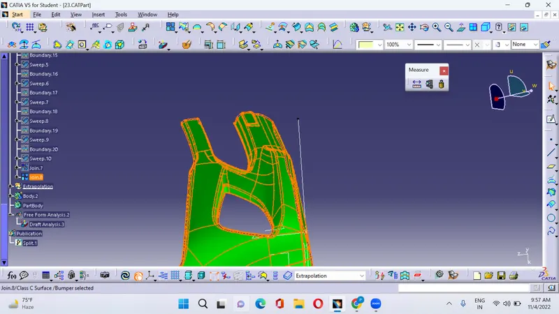
Draft analysis is shown in the below figure
Conclusion:
1.From the draft analysis the obtanied C surface color is both red and blue it means that the C surface cannot clear the draft direction for this if the C surface is parallel to the tooling direction then 3 degrees should be taken with reference to the tooling axis if the C surface is perpendicular to the tooling Axis then the sweep angle is 90 degrees with reference to the surface.