Week 8 - Challenge 4 - Bumper
BUMPER DRAFT ANALYSIS AND DESIGN:
- OBJECTIVE:
- To do Draft analysis and Design the Bumper with the help of Class-A, Class-B, Class-C, and Tooling axis.
- TOOLING AXIS
- Firstly, I have to create a tooling axis.
- Because to move further we have to check the input surface condition.
- For that, a draft analysis of the surface is most important.
- To perform a draft analysis, a tooling axis is required.
- So, there are many methods that exist to create a tooling axis such as the direct method, bisecting method, etc.
- I'm selecting a direct method for creating the tooling axis because the surface can easily get clear.
- Using the direct method, I created the tooling axis (refer to the pic below).
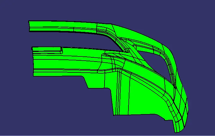
- Class-A surface is generally an aesthetic surface of automotive parts of the car (refer to the pic below), which is given here as input.
2. CLASS-B SURFACE:
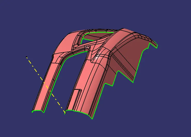
- Class B surface is used for plastic molding purposes. For providing the product, a Class-B surface is used mostly.
- After creating the tooling axis, I will next make the Class B surface.
- Refer to the pic below, which shows the Class-B surface.
- For making a Class B surface, I will use the following command:
- Offset: To offset the class-A surface
- Boundary: Select the required boundary if required.
- Extraction: In this, no boundary is required, so go to extract the flat surface of class A.
- Untrim: After extraction, Untrim those surfaces.
- Extrapolate: extrapolate those surfaces.
- Trim: trim those extrapolated surfaces to get the desired surface.
- Sweep: There are many patches that simply can't be solved by extraction extrapolate strategies. So, to fix those patches sweep is required.
- Multi-section solid: It's required a profile and guide curve and accordingly it creates a surface.
3. CLASS-C SURFACE:
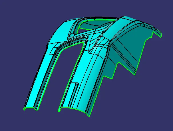
- Class C surface generally connects the Class-B surface to the Class A surface.
- Referring to the below pic, Class-C Surface is shown.
- To create a Class -C surface use the following command:
- Boundary: pick the boundary for the next operation.
- Swept: swept the selected boundary.
- Extrapolate: surface can't join properly, so I used to extrapolate those surfaces.
- Trim: trim those extrapolated surfaces and get the required surface.
- Join: now join those surfaces with each other and form a single surface.
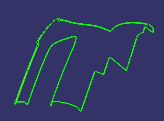
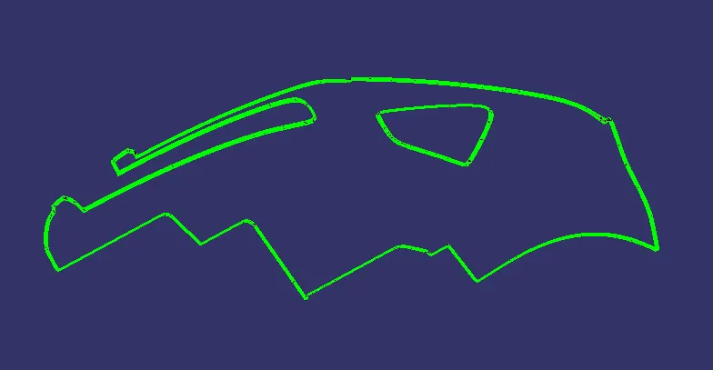
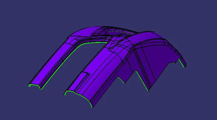
- A+C surface:
4. Final Operation to get Bumper:
- Firstly, Select the join operation and join the class A and class C surfaces.
- Trim those join with the class B surface.
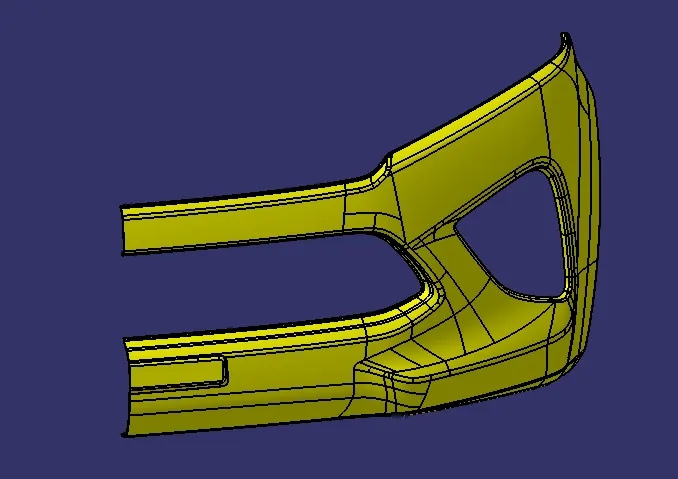
- After that, I got the final Bumper.
- As the surface is hollow from the inside, for this go to the part workbench and select the close surface.
- After that analyze the output surface with draft analysis.
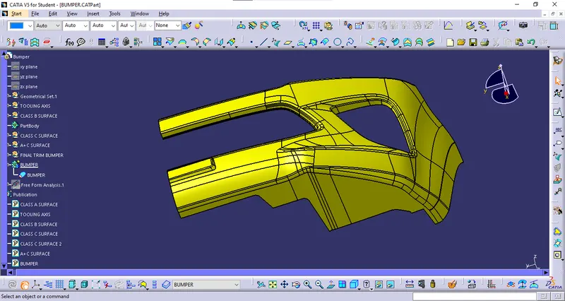
- So, in this way, we got our final design as a Bumper (Referring to the pic below).
- DRAFT ANALYSIS:
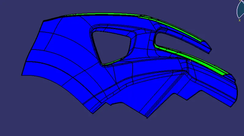
- To analyze the designed bumper, I made an analysis by setting the draft angle at 3 degrees.
- As it mostly clears the surface (refer to the below-given pic)