Week 8 - Challenge 4 - Bumper
REPORT
Draft Analysis
- Draft allows a part to release from the mold. Draft is required on all parts in the direction of the mold movement in order to allow parts to release or eject from the mold properly.
- Draft is the angle in the part is tapered to allowed it to release. As the part cools it tends to shrink to the core side of the mode.
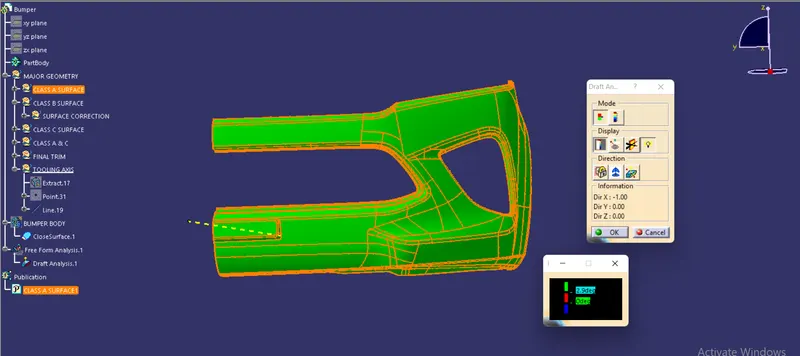
- The given Class-A-Surface is analised for draft angle.
- The Draft Analysis Toolbar in CATIA V5 is used. After importing the Class-A-Surface the View Mode Customization is selected and in the custumization windows, in the shading section Material is selected.
- After that the Draft Analysis Toolbar is selected and in the draft analysis window the Compass is selected and it is repositioned at top side of the Tooling Axis.
- Then the surface is selected and the surface colour is shown according to the draft given to it.
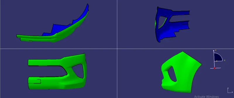
- For Draft angle above 2.9 degrees the surface is colored Green, for Draft angle with 0 degrees the surface is colored Red and for draft angle less than o degrees the surface is colored Blue.
- It is observed that for the given Class-A-Surface the observed Color is green, so the draft given to the surface is sufficient.
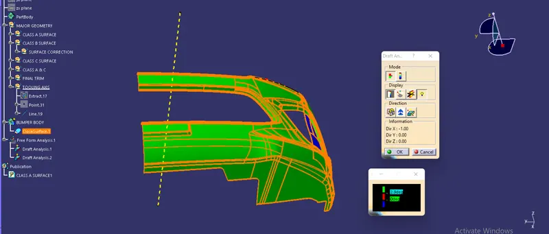
- After the surfacing and close surfacing, the Final Plastic Part is Analysed and the draft is observed to be above 2.9 degrees which is sufficient.
Draft analysis for the given Class-A surface
Draft analysis for the final plastic component
Screenshots of the solid model with the proper color code of the draft angle in various orientations
Tooling Axis
- Tooling axis indicates the direction through which the tooling (molding, core and cavity movement) is done.
- The axis should be created in such a way that all the parts of the body can be created through that axis.
- For the given Class-A-Surface the tooling axis is in the direction normal to the selected surface.
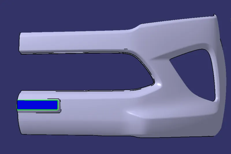
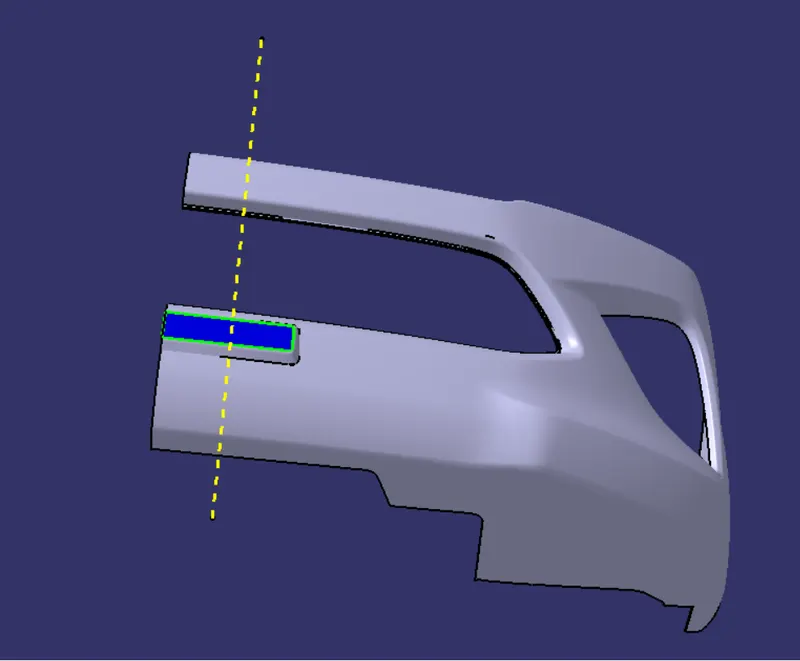
- The line normal to this surface cleares all the surfaces for draft angles, since the given Class A is only one half side of the bumper. A line made normal to the selected axis will clear all the surfaces to the other side as well.
- While considering a full bumper body the so formed toolng axis will be adequate in clearing all surfaces in a sing molding process.
- Thus this formed line is the required Tooling Axis. Creation of Class-C-Surface is done perpendicular to this line to form the required plastic body.