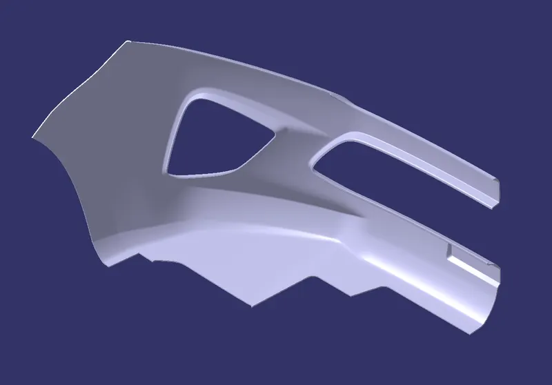
Week 8 - Challenge 4 - Bumper
Week 8 - Challenge 4 - Bumper
AIM:
To make a model from the provided class-A surface.
OBJECTIVE:
- To create a tooling direction.
- To perform draft analysis for given A-Surface and prepare the final close body.
- To design the Bumper plastic component by creating the B-Surface and C-Surface using the given Class-A surface.
- Take the Thickness of the component to be 3 mm.
INTRODUCTION :
The input of the product designer is in the form of the A-class surface. The job of the product designer is to create the B and C surfaces keeping all the aspects for the mold.
CLASS-A SURFACE:
A surface made by the designer which is given as an input to the plastic modeler to work on. It is aesthetic surface and the outer most surface.
- Visible surface and aesthetic look.
- Surface with textures.
- Surfaces provided by customer(OEM).
- Don't have any features like(rib, snap, bosses, etc) on class A surface.
- Class A surface is made from scanned data with different software like alias etc.
- Surfaces which are having CURVATURE CONTINUITY IS CALLED class-A.
CREATING TOOLING AXIS :
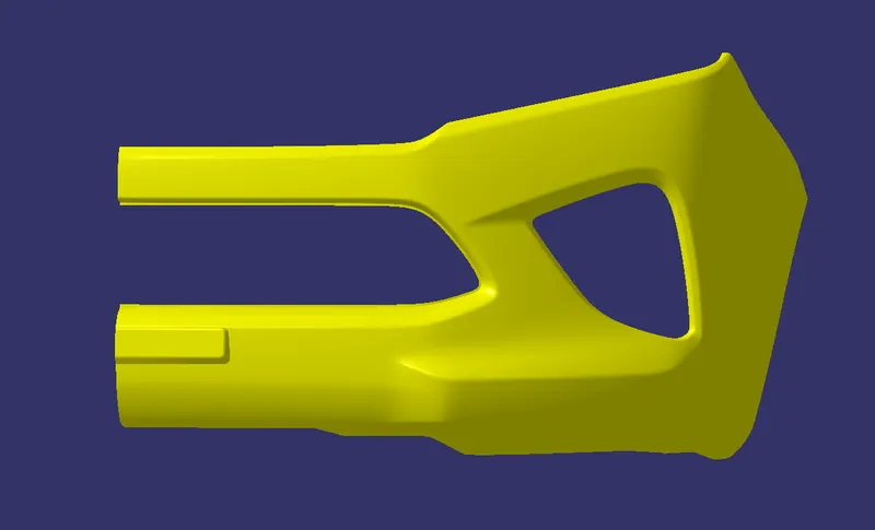
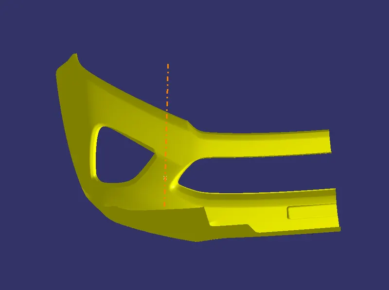
It is nothing but the direction in which the mold opens and closes the draft angle needed to be provided by considering this tooling axis.We can create a tooling axis by using the bisecting method.
While creating the tooling direction in given class A surface. Chose the one suitable Base and Side wall and draw the line direction of axis.
- Intersected the plane on class A
- connected two out points by line.
- Excruded the line by taking the point on the surface
DRAFT ANALYSIS :
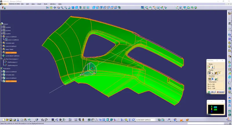
The draft analysis of the Class A surface has shown the draft angle should be more than 3 degrees and this can be clearly observed from the above images that the surfaces have an angle of more than 3 degrees.
- First, we analyze the model and then choose a dummy axis in the x and y directions.
- As we intersected to proceed we observed that the side walls are not given any draft. Hence we assume the axis normal to the base surface and parallel to the side walls.
- This surely will create problems because a minimum draft has to be provided.
- As the class-A surface is made by another designer only he is authorized to make changes, so we look over this to complete the coin holder for practice.
- Now we go to insert< analysis< draft analysis and follow the usual procedure to do the analysis.
- Align the compass and click on the surface and as expected the model is mostly in red color i.e. negative draft with respect to the axis.
- To correct it as best as we can we moved the compass a bit till we got most of the surfaces in green and locked that position.
After hitting ok, we change the direction of the line from the z-axis to the compass direction. - The axis will align itself accordingly.
NOTE: as the side wall does not have a draft, this result was expected and a few areas need correction. But still, we are moving forward to
complete the model.
DRAFT ANALYSIS FOR CLASS A SURFACE
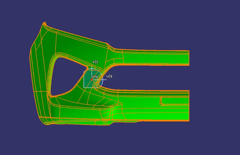
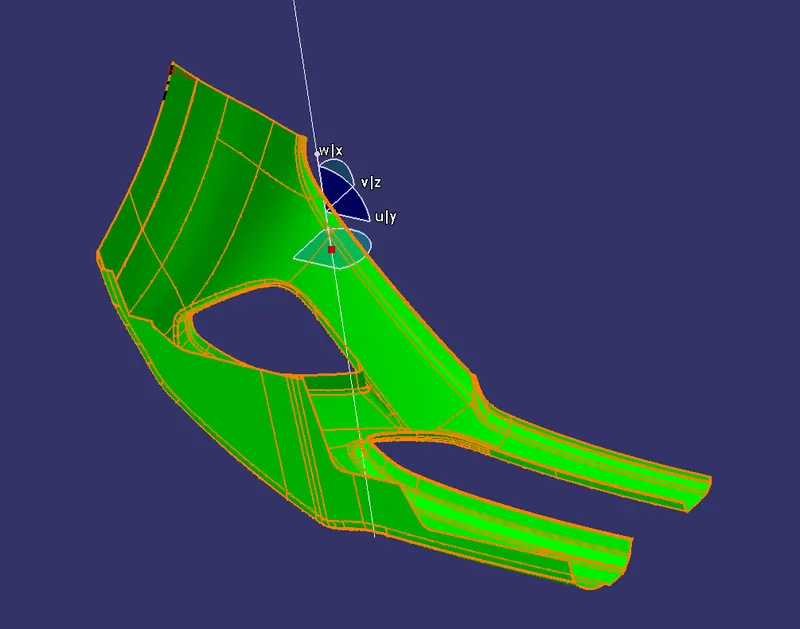
DRAFT ANALYSIS FOR CLASS C SURFACE
FRONT VIEW
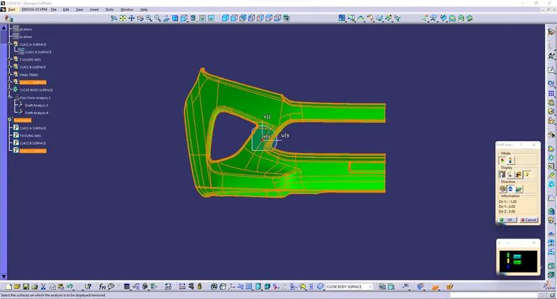
SIDE VIEW
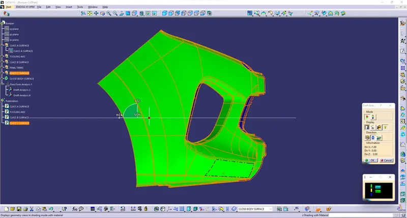
TOP VIEW
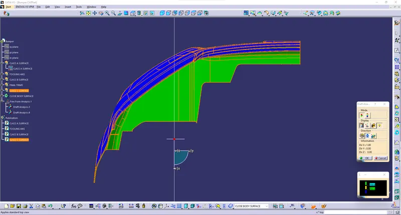
ISOMETRIC VIEW
CLASS-B SURFACE:
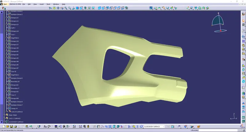
A surface below a certain thickness from the class-A surface is class-B surface .This is the surface that contains Engineering aspects of a model.
- Invisible Surfaces.
- Surface mostly don't have textures.
- Surface needs to be created according to the class-A surface.
- Having all features(Rib,boss,snap etc) in B-side surface only.
- Surfaces which is having tangent continuity is called class-B.
CLASS-C SURFACE:
A surface that joins class-A and class-B surfaces is a class-C surface.
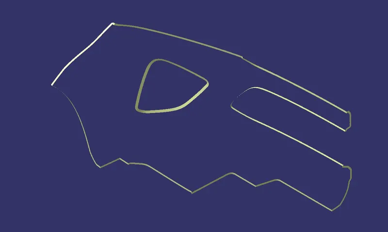
Check the connectivity of the Class A Surface Ensure that there is no gap between the component, using join command. We can visually check it or by clicking boundary command. It has a boundaries outer. Therefore first check completed.
FINAL CLOSE C SURFACE :
FRONT VIEW
SIDE VIEW
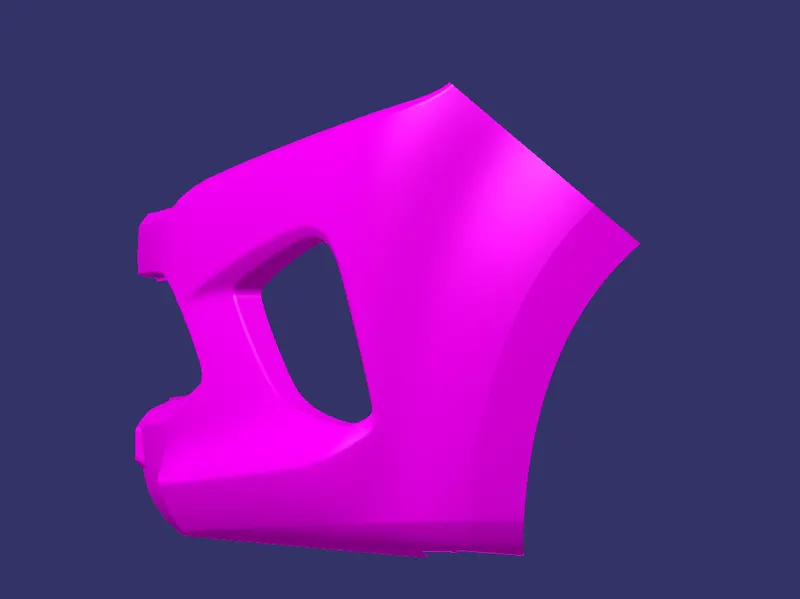
TOP VIEW
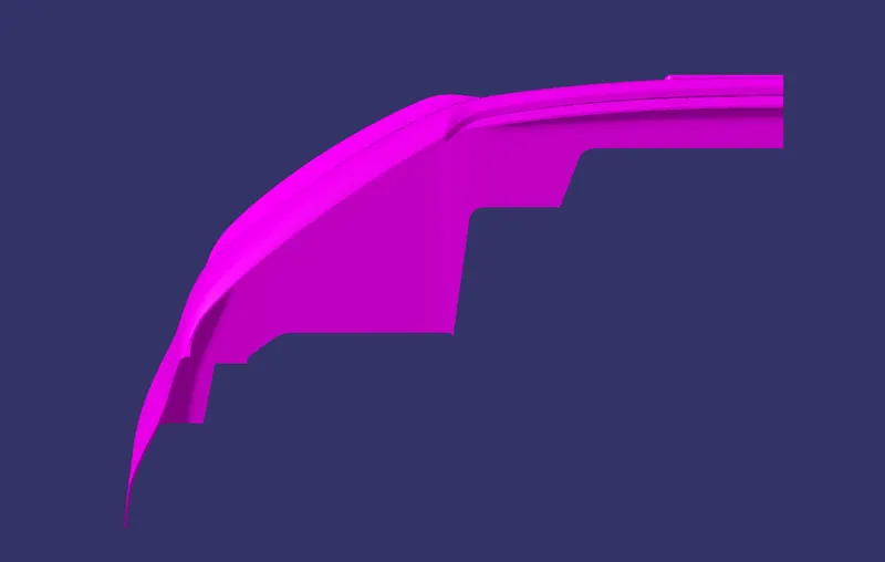
ISOMETRIC VIEW
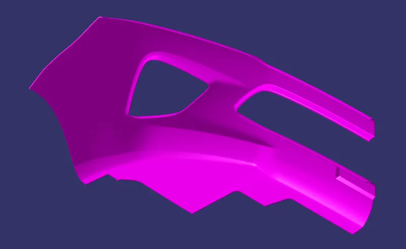
MULTIVIEW
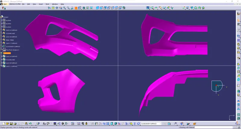
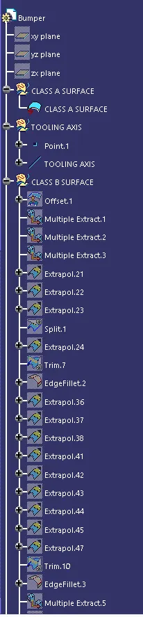
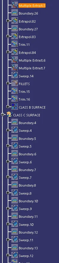
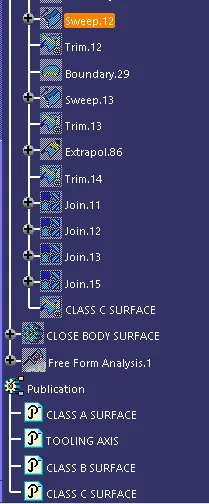
FEATURE TREE
FINAL COMPONENT :
FRONT VIEW
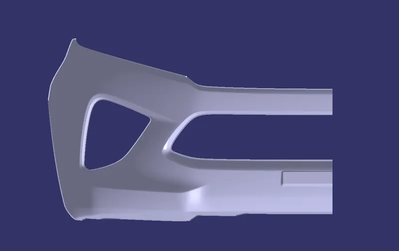
SIDE VIEW
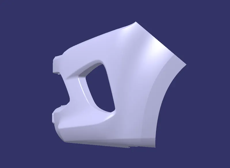
TOP VIEW
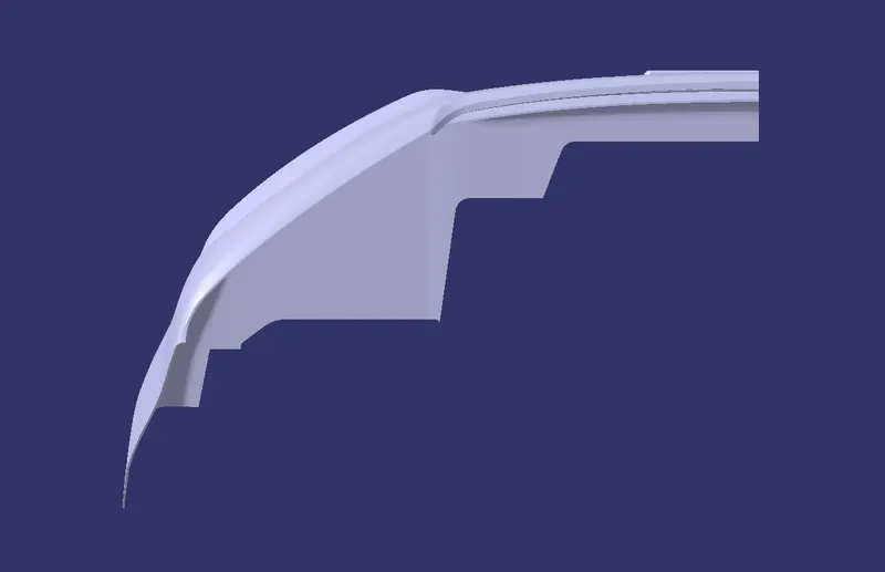
ISOMETRIC VIEW