Radar Mast & Final Assembly of Yacht
MODELLING AND ASSEMBLING OF YACHT
Objective:
To Design all parts of the yacht and assemble all the Parts with fully Defined sketches.And Render the yacht model by adding appearance, Decals, lights,Cameras and Background scenes.
Introduction:
- (SolidWorks) is a mechanical 3D CAD (Computer-Aided Design) Software used to create 2D & 3D models. It helps to design products,Better, faster, and more cost-effectively.
- (Yacht) A yacht is a type of boat which is mainly used for recreation.It usually has a cabin, so it does not need to return to the harbour overnight. Originally, yachts were sailing-boats, but now there are also motor yachts. The name comes from the Dutch word jachtschip, which originally meant hunting-boat or fast boat.
- In the process of modelling a sunseeker predator yacht we design a part or model by using initial 2D sketches,and then we turn them into 3d models using the tools like surface tools,featuring tools etc.
- Assembling and visualization plays an important role in any model that we create in a cad software.
- Here almost 90% of the model is modelled using surface modelling and the we make them into a solid body.
- most of the part bodies are modelled using blue prints only.
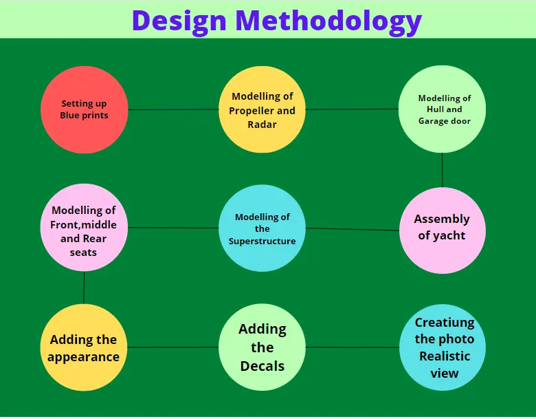
Design Methodology:
Description of Parts,Tools bar and Sketch tools:
FEATURE COMMANDS
- Extruded Boss/Base- One of the oldest commands in the SOLIDWORKS software is the boss/base extrude command. An Extruded Boss/Base feature will allow us to take a 2D sketch and add thickness to it in the third dimension.
- Extruded Cut- it's a tool to remove material by projecting a sketched section normal to the sketching plane.
- Split-Lines are used to divide model faces into two. Split lines are created like any other sketched feature. They can be one or more connected sketch entities. They must be oriented so that they will pass through model faces when projected normal to the sketch plane.
- Dome-It can add one or more domes to the selected planar or non planar faces. The software calculates the distance using the radius of the arc as a basis for the dome.
- Pierce Relationships - The Pierce relationship is used in sweeps. It can be thought of as a 3D Coincident relationship. In our spring, the circle will follow the helix Think of the helix as a thin piece of wire and the profile sketch as being drawn on a piece of paper. If we stick the wire through the paper at the centre of the circle, this would be a pierce relationship. When we perform the sweep, the paper will slide along the wire, held at the pierce point.
- Project Curve - Select Bi-directional to create a projection that extends on both sides of the sketch. The curve can be used as a path for a sweep.
- Composite Curve - We can create composite curves by combining curves, sketch geometry, and model edges into a single curve. Composite curve can be used as a guide curve when creating a loft or a sweep.
SURFACE COMMAND:
- Lofted Surfaces - Creates a lofted surface between two or more profiles or sketches. Specify start and end constraints and add guide curves to control the path shape.
- Boundary Surfaces - The boundary surface feature lets us to create surfaces that can be tangent or curvature continuous in both directions (all sides of the surface). In most cases, this delivers a higher quality result than the loft tool.
- Extruded Surfaces - Extrudes a sketch or selected sketch contours in one or two directions two create a surface features.
- Revolved Surfaces - Revolves a sketch or selected sketch contours around an axis to create a surface features.
- Swept Surfaces-It Sweeps a closed profile along an open or closed path to create a surface feature. It uses a tangent plane at the end of the path so that the path is normal to the swept surface.
- Filled Surfaces - Patches a surface within a boundary defined by edges, sketches, or curves. We can Nse constraint curves to fill surfaces and adjust resolution control to improve surface finish.
- Ruled Surfaces - Inserts ruled surfaces in a specified direction from edges. Tangent to surface, Normal to surface, tapered to vector, perpendicular to vector or sweep can be selected. We can also trim and knit the surfaces and remove any connecting surfaces.
- Trim Surface-It trims the surfaces where a surface intersect with surface, a plane or a sketch.
- Knit Surface - It combines two or more adjacent, non-intersecting surfaces into a single surface body. The surfaces must joint at an edge. If the resulting knit surface encloses a volume, we can create a solid body from the Property Manager.
- Move/copy surfaces - Moves or copy surfaces about a plane or a sketch.
- Offset Surface-Offsets surfaces using one or more contiguous faces. This tool helps us to create an offset surface with gaps.
- Extend Surface-Extends one or more edges or faces on a surface,based on end condition and extension type.
- Mirror surfaces - A mirror feature is a copy of a selected feature,mirrored about a plane or planar face. A mirror sketch entity is a copy of a selected sketch entity that is mirrored about a centerline. If the original feature or sketch is modified, the mirrored copy is updated to reflect the change.
- Reference plane-We can create planes in part or assembly documents. We can use planes to sketch, to create a section view of a model, for a neutral plane in a draft feature, and so on.
- Projected curve - A projected curve is typically used either in sweeps and lofts as path or guide curve. There are two types of projected curves.
- Split line - The Split Line tool projects an entity (sketch, solid, surface,face, plane, or surface spline) to surfaces, or curved or planar faces. It divides a selected face into multiple separate faces. We can split curves on multiple bodies with one command.
- Split point - We can split a sketch entity to create two sketch entities Conversely, we can delete a split point to combine two sketch entities into a single sketch entity.
- Fillet- A fillet is an internal rounding of a corner or edge in a sketch, or an edge on a surface.
PARTS:
Blueprint Setup:
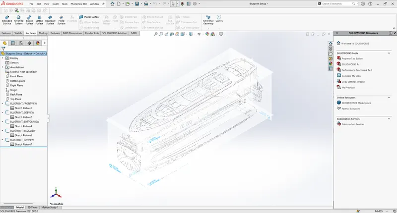
Blueprint is basically a design plan or technical drawings of different orthographic views of a product. The main motto of the blueprint is to bring out the exact same shape and form of the product as designed by a designer. It also ensures the accuracy and the proportion of the product. Designing a product without a blueprint may lead to multiple errors, unnatural proportions and improper dimensions. A proper blueprint setup omits all those problems.
To set up a blueprint, we use sketch mode in SOUDWORKS in each plane. In this case, the images provided for the front view, side view, top view, back view, and top views are added in respective planes. One very important thing to note while setting up a blueprint is the size of it. As all the parts are going to be designed laying up the blueprint and taking its reference, it is very crucial to maintain the correct and real size of the blueprint in the very first step. It can either be adjusted manually with the dimensions or by adjusting the scale bar.
Methodology
- Select a Plane & select a 2d drawing option & go to Tools- Sketch tool-Sketch Picture.
- Browse the Image & change the dimensions as per requirement & use transparency tab & chose full image for convenient sketching & name the views.
- Repeat the above steps & name it as Front view, side view, Top view, Back view. - change the names of the planes as front plane, bottom plane & mid plane & Arrange the blue prints in a sequential order.
Propeller:
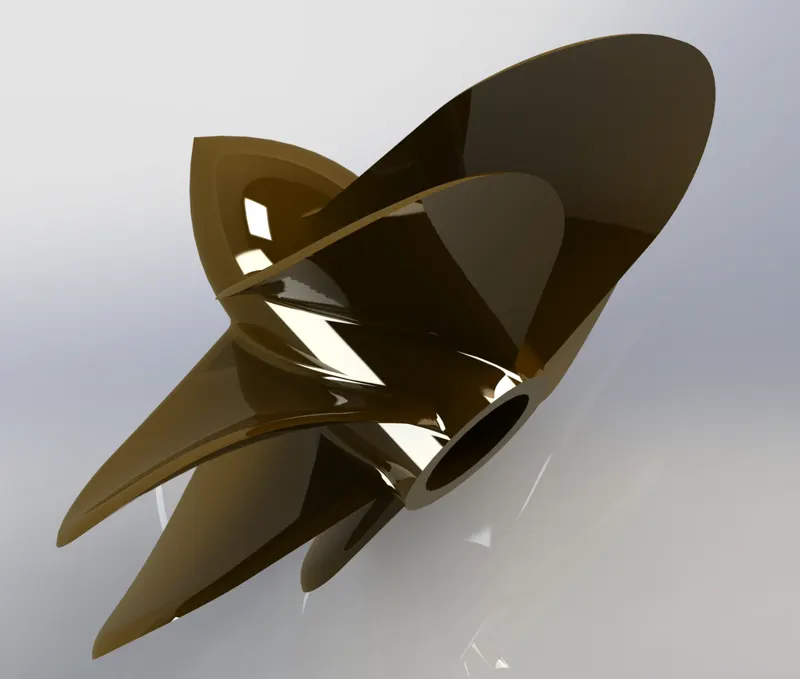
Propeller is a type of fan blade which is conected with the Powerful motor to Producing force to moving the yacht.
Hull:
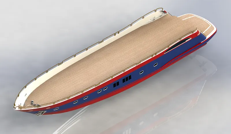
A hull is the watertight body of a ship or boat. The hull may open at the top, or it may be fully or partially covered with a deck. Atop the deck may be a deckhouse and other superstructure, such as a funnel, derrick, or mast. The line where the hull meets the water surface is called the waterline.
Hull is the main part of the Yacht. It is the giant component which extends 108ft long. It is the structure which holds all the other components of a marine vehicle. It is the part which is enclosed and water-lift is created for the movement of the vehicle on the surface of the water. The curves are sketched as close as the blueprints from 2 different views and are projected to form a 3D curve. 3D sketches are also used in this part. The Hull for this Yacht was created using the surfaces made out of the projected curves using the blueprints sketches. It consists of parts like railings, bow, deck, pulpit, anchor, garage, windows, etc.
Methodology
- The hull is a watertight body of a vessel which may be open or may be partially covered with a deck.
- Hull has several watertight decks and bulkheads as the major transverse membrane.
- The intermediate member of the hull consists of girders, webs and stringers.
- Depending on the structural arrangements, there may be longitudinal members for strengthening purpose.
COMMANDS USED TO MODEL
In Sketch
- Line
- Spline
- Circle
- Rectangle
- Arc
- Slot
- 3-D Sketch.
- Sketch picture
In Surfaces
- Extruded Surface
- Revolved Surface
- Lofted Surface
- Surface Trim
- Surface Fill
- Surface Knit
- Delete Face
In Features
- Project Curve
- Chamfer
- Fillets
- Reference Plane Split
- Split Line
- Extruded BossBase
- Extruded Cut
- Mirror
RADAR:
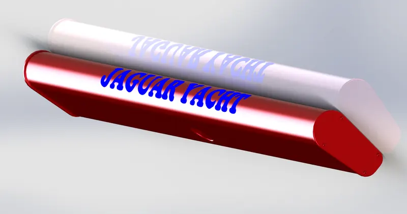
It is used to detect the object's position ,signals etc relative to the position of the yacht.
COMMANDS USED TO MODEL
In Sketch
- Line
- Text
- Circle
- Point
In Features
- Extruded Boss/Base
- Extruded Cut
- Sketch Pattern
- Fillet
- Mirror
- Split Line
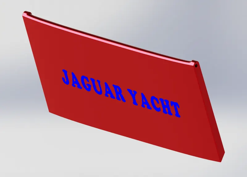
Garage Door:
A garage door is a large door on a garage that opens either manually or by an electric motor (a garage door opener). Garage doors are frequently large enough to accommodate automobiles and other vehicles. The operating mechanism is spring-loaded or counterbalanced to offset the weight of the door and reduce human or motor effort required to operate the door. Less commonly, some garage doors slide or swing horizontally. Doors are made of wood, metal, or fiberglass, and may be insulated to prevent heat loss.
COMMANDS USED TO MODEL
In Sketch
- Line
- Spline
- Circle
- Text
In Features
- Extruded Cut
- Reference Plane
- Fillet
- Shell
- Mirror
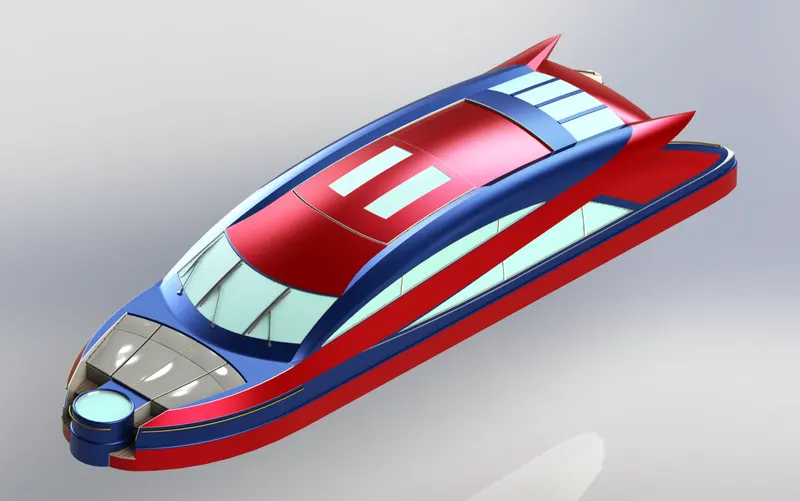
Superstructure:
The superstructure covers everything above the substructure, from walls to floors to roofing. The purpose of the superstructure is to enclose and divide space, as well as spread loads safely into the substructure.
COMMANDS USED TO MODEL
In Sketch
- Sketch Picture
- 3D Sketch
- Line
- Spline
- Circle
- Rectangle
- Center Point Arc
In Surfaces
- Extruded Surface
- Swept Surface
- Ruled Surface
- Knit Surface
- Trim Surface
- Extend Surface
- Filled Surface
- Lofted Surface
- Revolved Surface
- Fillet
- Chamfer
In Features
- Project Curve
- Reference Curve
- Convert Entities
- Split
- Split Line
SEATS:
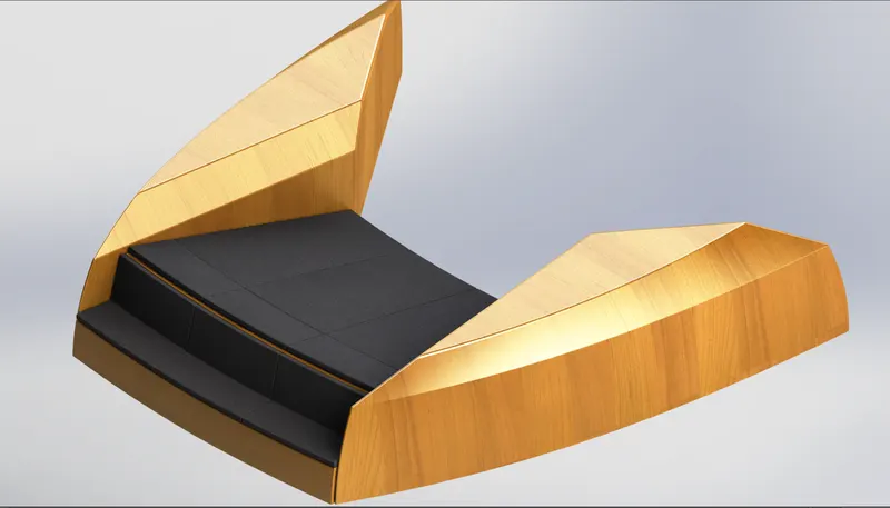
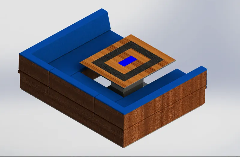
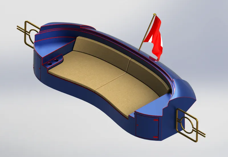
Seats are used for the purpose of giving rest to thre human body in relex positions. Mainly it made of metal,Wood and Ceramic concrete, etc. In this model we are design three types of seating arrangement such as Front seat , Middle seat and Rear seat shows in below figure.
COMMANDS USED TO MODEL
In Sketch
- Sketch Picture
- Line
- Spline
- Circle
- Arcs
- Rectangle
In Surfaces
- Swept Surface
- Extruded Surface
- Off-set Surface
- Filled Surface
- Knit Surface
- Ruled Surface
- Lofted Surface
- Trim Surface
- Revolved Surface
In Features
- Reference Plane
- Extruded Boss/Base
- Revolved Boss/Base
- Fillet
- Mirror
- Extrude cut
- Chamfer
- Dome
Front Seat
Middle Seat
Rear Seat
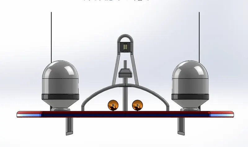
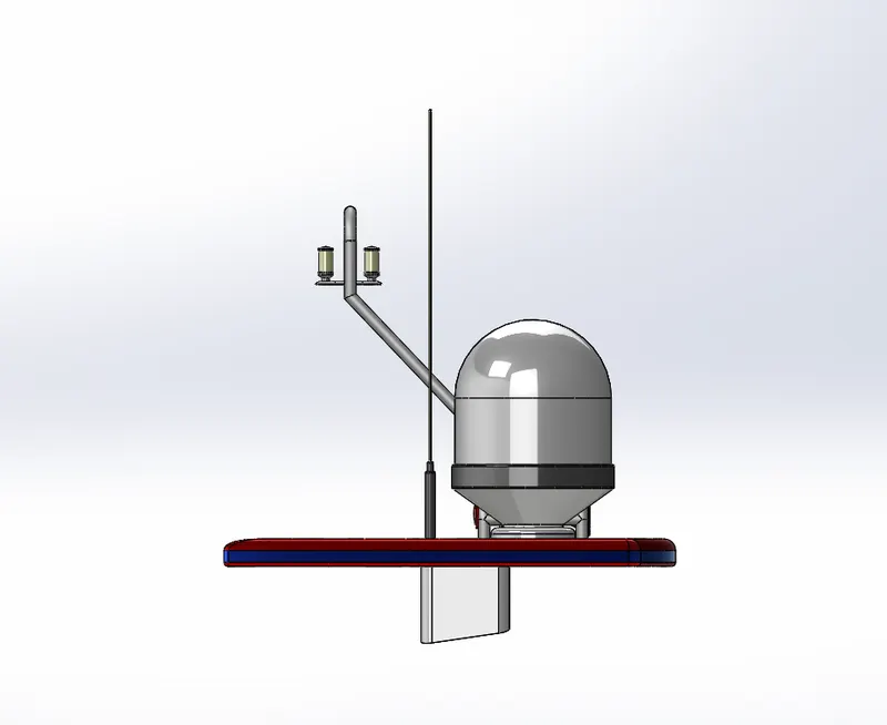
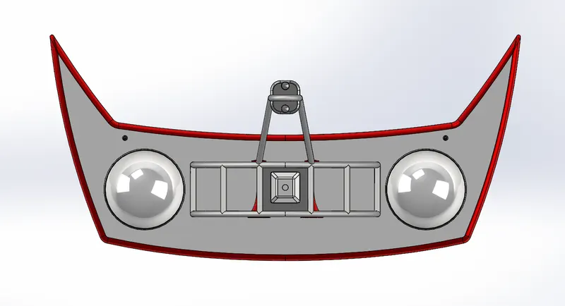
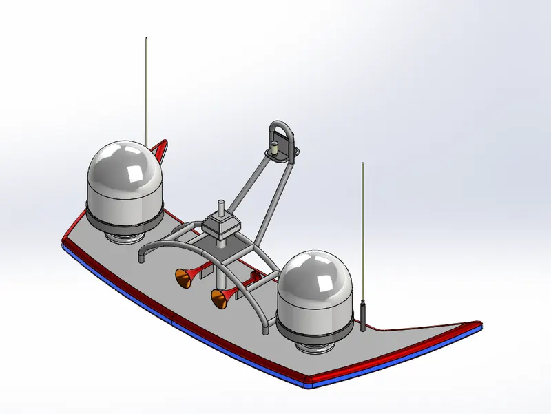
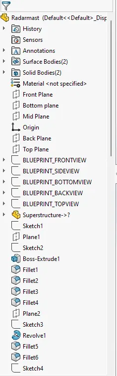
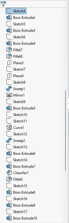
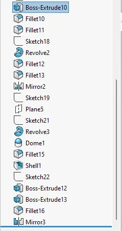
RADAR MAST:
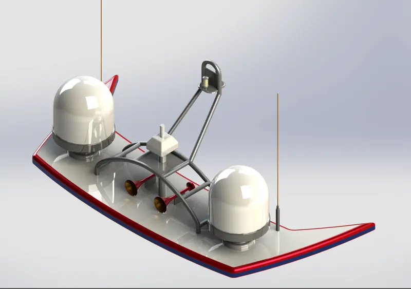
A mast is a vertical ship structure mounted on top of bridge and forward of the forecastle towards the ship's bow. It accounts for the support platform for the ships derrick and hold necessary equipment's such as radars, navigation light and ships horn in case of foremast. They are made of high tensile steel with added rigidity based on the size of derricks it holds. Other than that a ships main mast is also used to hoist ships flag.
Out of different parts of ship the main job of mast is to hold necessary equipment such as radar receiver, navigation lights, ships horn, flags and derricks in some case.
COMMANDS USED TO MODEL
In Sketch
- Sketch Picture
- Line
- Spline
- Rectangle
- Arcs
In Feature
- Extruded Boss/Base
- Lofted Boss/Base
- Revolved Boss/Base
- Swept Boss/Base
- Reference Plane
- Projected Curve
- Fillet
ASSEMBLY:
Assembling is the process of combaning the different parts with a sequence of joining through advanced mates like coincident, distance, angle, concentric, parallel, width, limit angle, etc.
Render model:
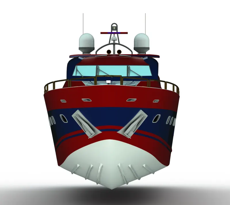
Front view of Yacht
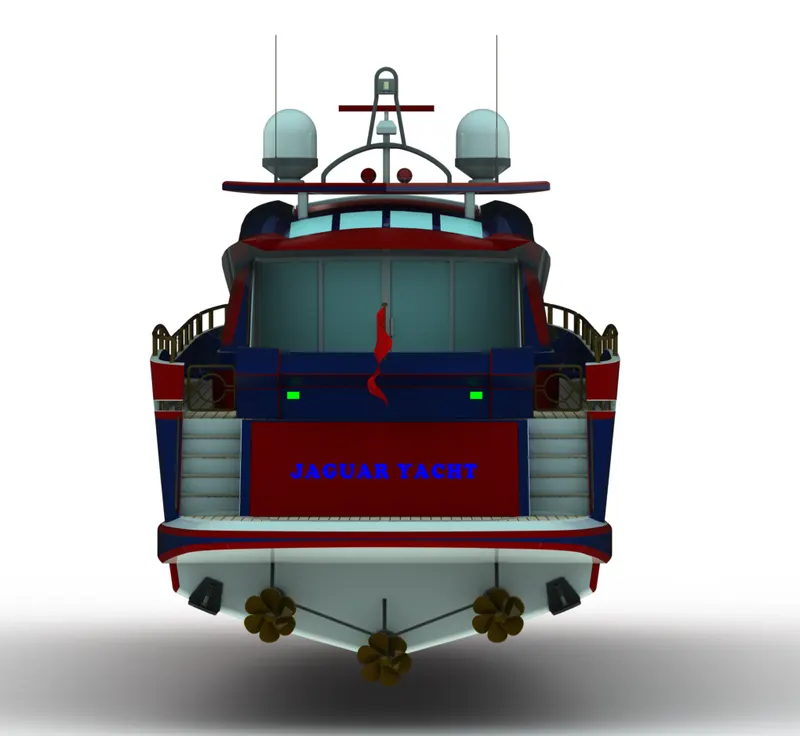
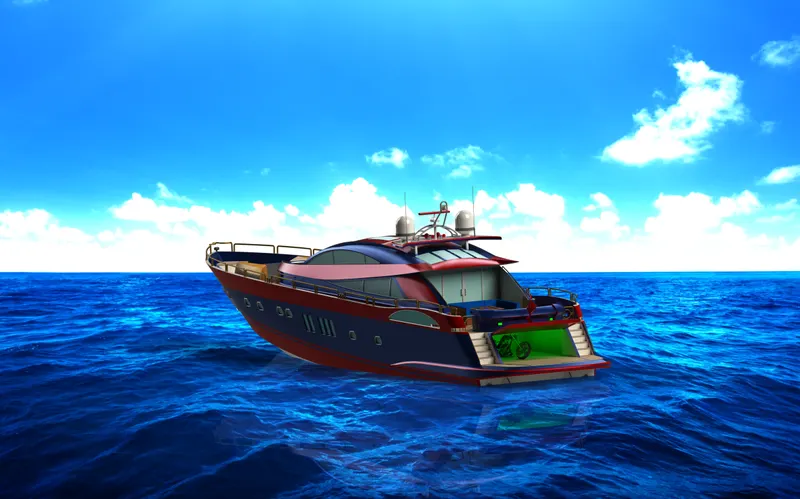
Backside view of yacht
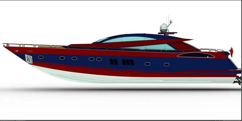
Side view of yacht
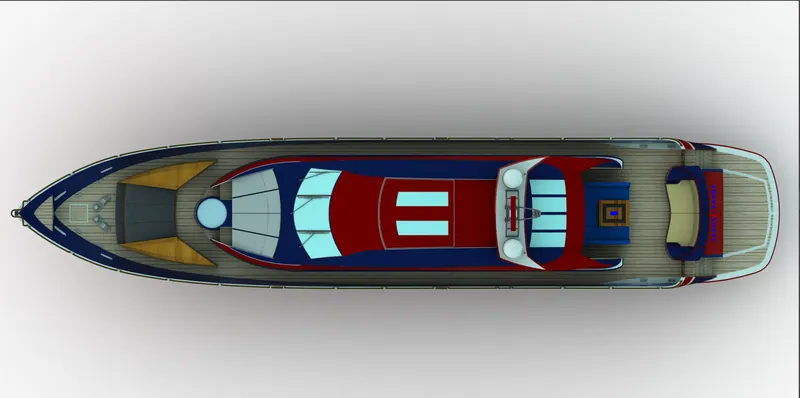
Top view Of yacht
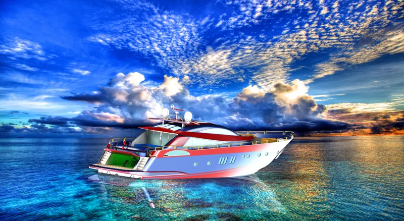
Isomatric view of yacht

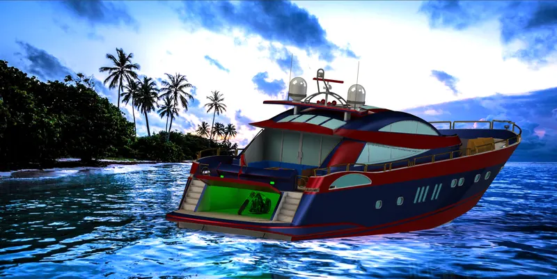
Photo Realistic Final Render of yacht
Photoview 360
PhotoView 360 is distinguished from RealView in that it is not a process of the GPU, and photorealistic renderings can be achieved regardless of the graphics card used. This is because it is entirely calculated on the CPU on your PC and is rendered in a sequential event and is therefore not dynamic. PhotoView 360 renderings are more photorealistic than RealView because light rays and reflections are more accurately calculated.
PhotoView 360 rendering supports:
- Self-reflection (reflection of objects in one another)
- HDRI (environmental) lighting.
Appearances
Appearances control the way the surfaces of the model look. They can be applied at the assembly, part, body, feature or face of a model. All surface of a model have an appearance applied to them.
Photorealistic Rendering
Photorealistic rendering is the process of photography except that we are using a computer model instead of a physical model. Prior to actually producing a product we may need to show the customer what the product will look like or we may need to produce marketing materials.
The PhotoView 360 software
PhotoView 360 is a software solution from Solidworks, fully integrated into the Solidworks software to create photorealistic images directly from Solidworks models. Renderings may be created from Solidworks parts and assemblies ,but not for drawings.
Procedural Appearances
Procedural appearances are defined by some procedure and consist of one or more colors and the way the appearance reacts to light. Procedural appearances can be thought of as 3D, that is they go all the way through the part. This is like adding dye to a plastic to be injected; the color will go all the way through the finished part.
Texture Appearances
Texture appearances are applied like wallpaper. During application, they can be stretched, shrunk, rotated, and reoriented to make them fit the surface. The pattern will be duplicated as many times as necessary to cover the entire surface.
Lighting
Lights may be added in the same way a photographer adds lights when taking photographs. PhotoView 360 uses the same lights as SolidWorks but also uses lighting from the rendering environment or scene. PhotoView 360 has the sophistication to trace light rays and reflections.
Scenes
Each SolidWorks model is associated with a PhotoView 360 scene, for which you can specify properties such as environments and backgrounds. Scenes help to put products in context.
Decals
Images, such as company logos, can be applied to models.
Output
The rendered output from PhotoView 360 can be viewed on the screen, or saved to a graphics file.
Options
PhotoView 360 has its own options. Options allow you to customize the PhotoView 360 settings to reflect your preferences. Options are divided into Output Image Settings, Render Quality, Bloom, Contour Rendering and Direct Caustics.
CONCLUSION:
By this project have learned...
- How to design a part or a model with proper 2D sketching and dimensioning.
- How to make a fully defined sketch. How to model a part or component using different features like surface modelling and solid modelling etc...
- How to make an assembly by using proper mates.
- How to make a photo realistic view of a model by using
- photoview360 and solidworks visualize.