Week 8 - Challenge 4 - Bumper
BUMPER:-
Car bumpers feature protruding shrouds of plastic or metal, called bumper covers, that surround energy-absorbing materials. They are designed to absorb impact to the front and rear of vehicles and minimize low-speed collision damage.
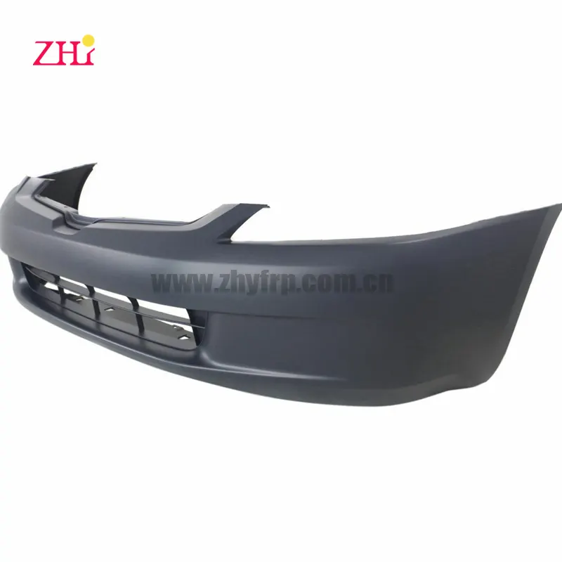
DESIGN BUMPER BY GIVEN CLASS A SURFACE
CLASS-A SURFACE:
a surface made by the designer which is given as an input to the plastic modeler to work on. It is aesthetic surface and the outer most surface.
given A class surface:-
TOOLING AXIS:-
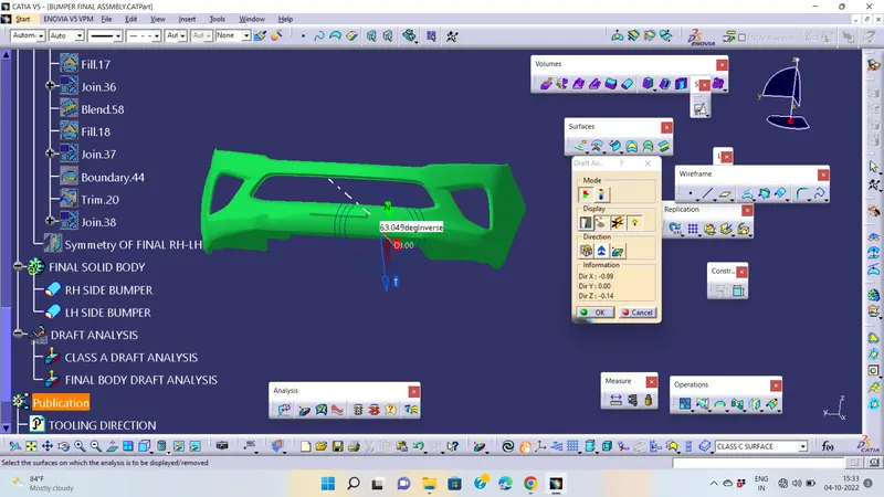
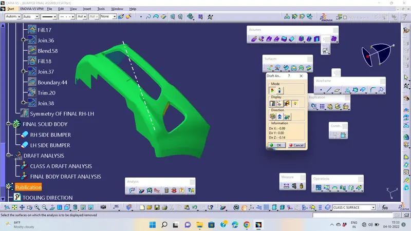
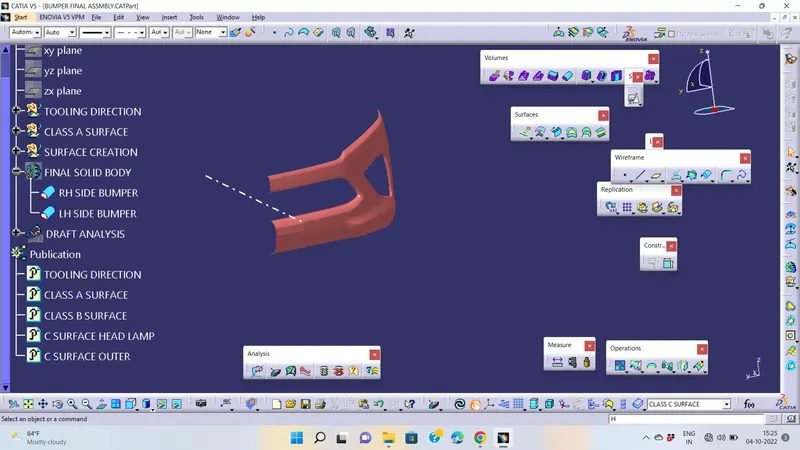
To create the tooling axis, I extracted a surface from class A and created a point in the middle of the surface by using the point command. Now, I performed a draft analysis check from that line whether the created tooling axis is in the correct position or not. If, in the draft analysis check the surface highlighted with green colour on both sides of the surface the tooling axis is in the correct position and direction.
DRAFT ANALYSIS:-
First we analysis the model and then choose dummy axis in x and y direction.
As we intersected to proceed we observed that the side walls are not given any draft. Hence we assume the axis normal to the base surface and parallel to side walls. This surely will create problems because a minimum draft has to be provided.
As class-A surface is made by other designer only he is authorized to make changes, so we look over this to complete the coin holder for practice.
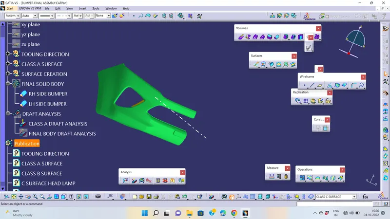
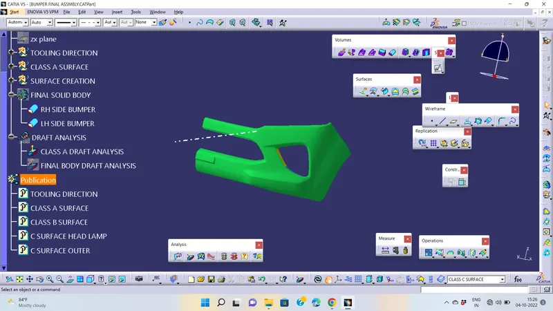
Now we go to insert -analysis -draft analysis and follow usual procedure to do the analysis.
CLASS B SURFACE:-
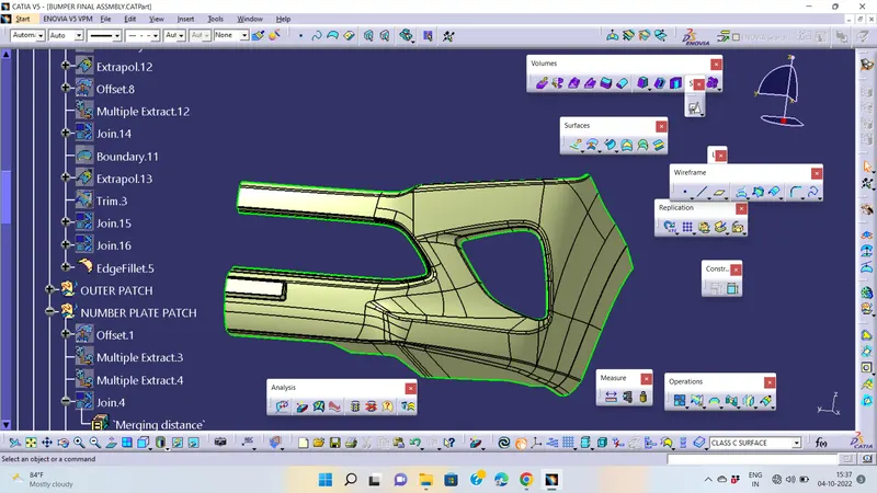
To create the class B surface, offset the class A surface inside as per our thickness requirement (here the thickness is 3mm, so I offset the class A to 3mm inside). Once the offset is created, we can observe some patches on the offset surface by taking the boundary for the offset surface, those patches are formed due to the fillets on the class A surface. We need to cover those patches with the help of the multi-section surfaces command by extracting the patch boundaries. Once all the patches on the offset are covered properly join all the patches with the offset surface, to get the replicated surface of the class A surface.
CLASS-C SURFACES:-
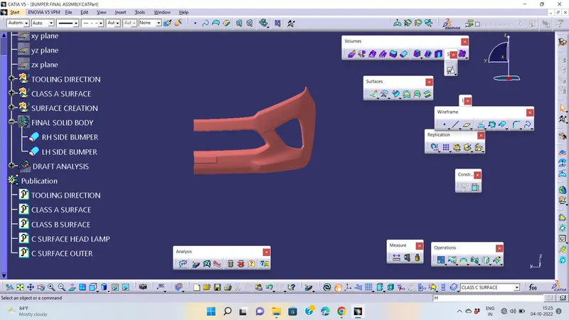
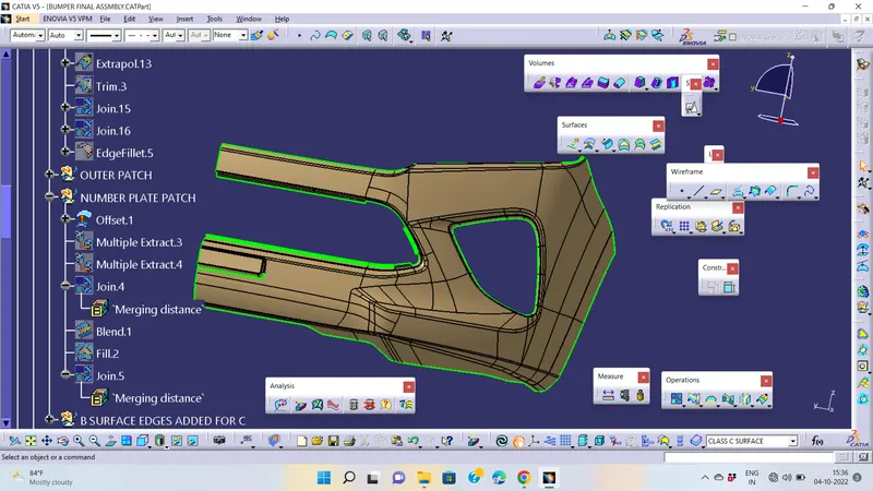
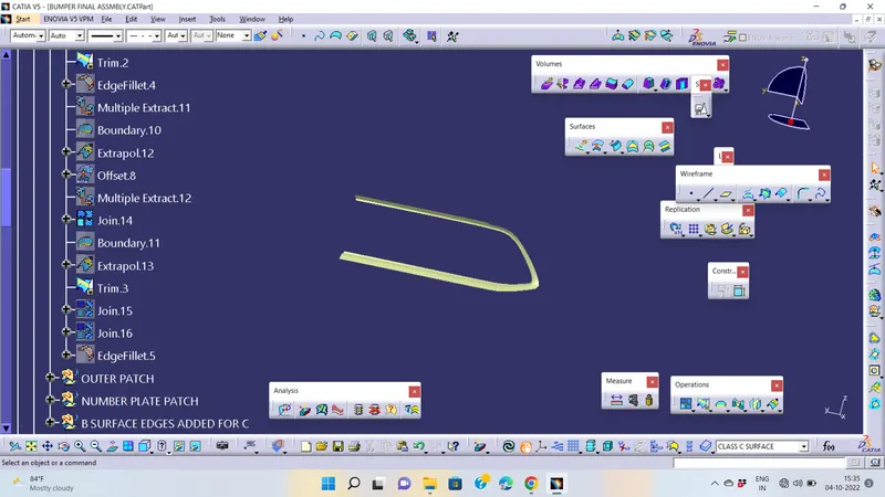
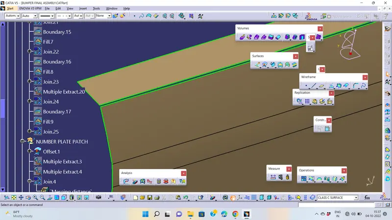
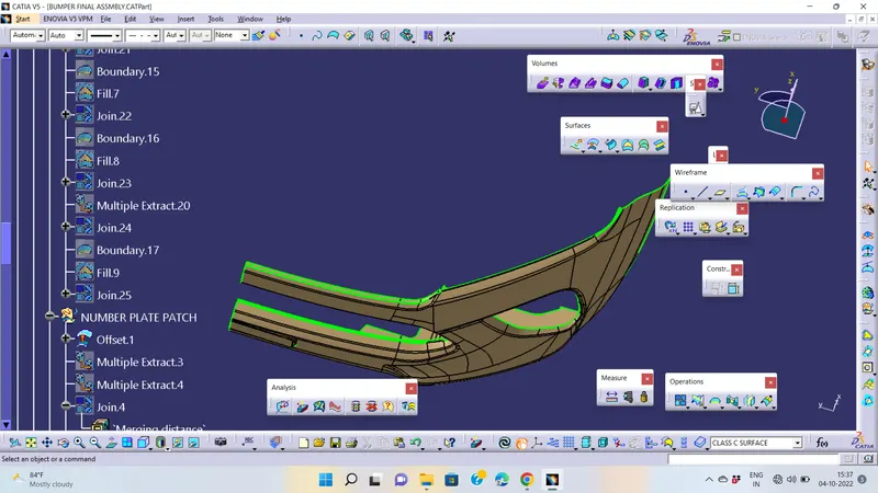
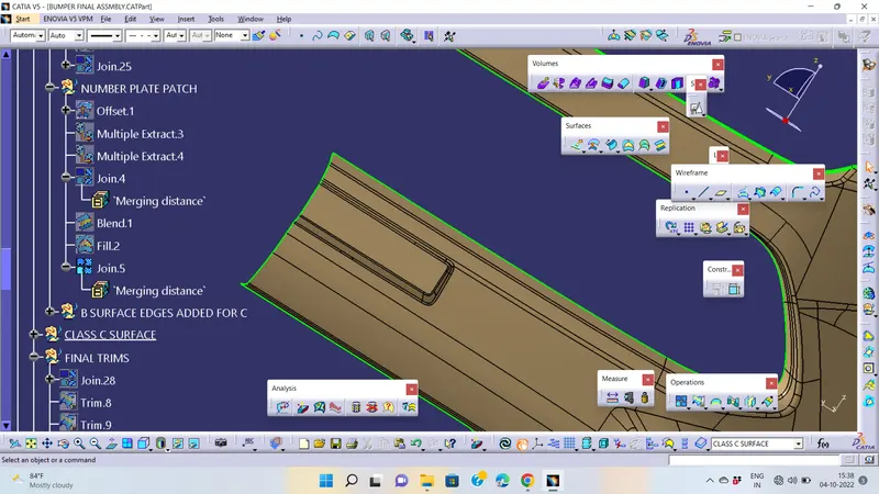
In this model, unlike the earlier models, we have used parallel tooling axis. Hence we cannot use ‘with draft direction’ option under sweep.so we go with refrence surfaces
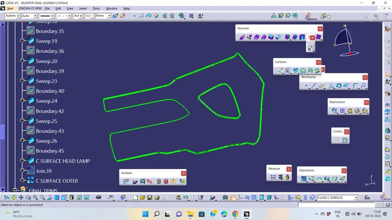
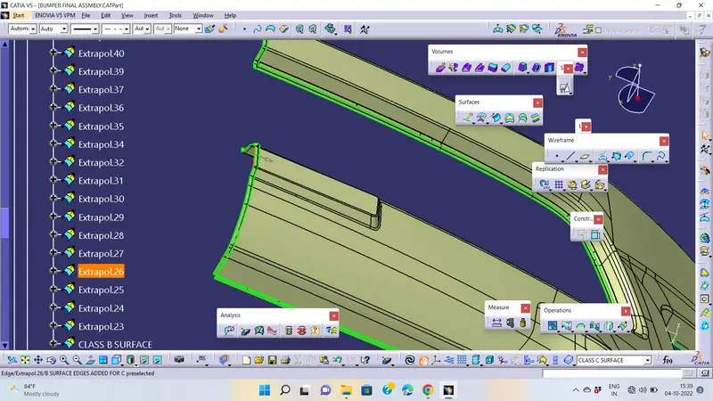
for using sweep with refrence surface we have give 3 degree or 93 degree angle to c surface, because draft angle is very important for plast parts ,so i have added 3mm extrapolate in every face
FINAL SURFACE:-
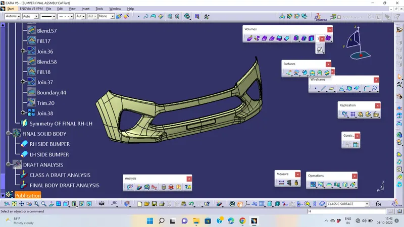
SURFACE TO SOLID BODY:-
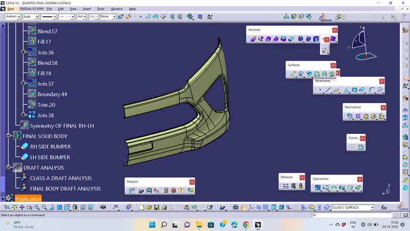
To create the solid part body from the closed surface, I used the closed surface command in the part workbench.
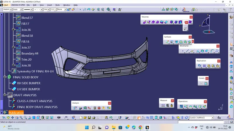
FINAL DRAFT ANALYSIS :-