Week 8 - Challenge 4 - Bumper
Input:
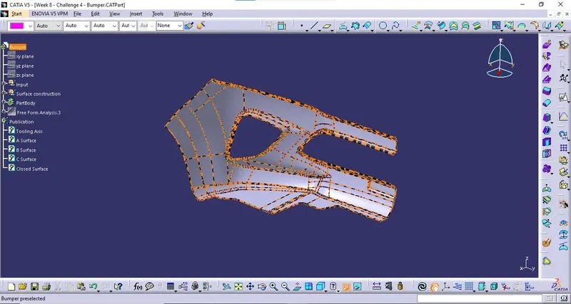
The input was given as Class A surface.
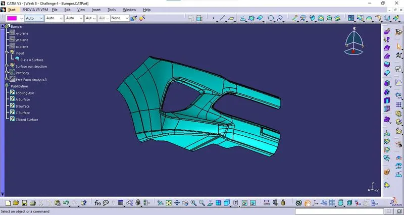
Tooling Axis:
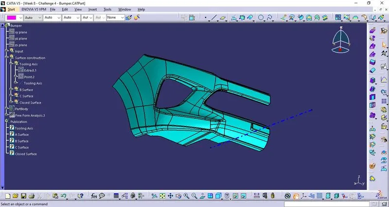
The component has walls that are perpendicular to the base of the component. Since the natural tooling axis was taken, (i.e) the axis normal to the base is taken as the Tooling axis.
Draft Analysis of Class A:
Draft analysis is done on the Class A Surface with respect to the Tooling Axis created.
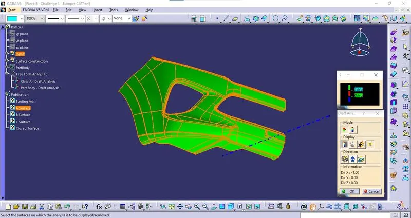
The minimum draft angle was given as 3 Degrees.
Class B Surface:
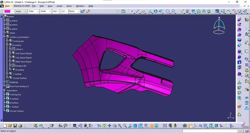
Class B was created by offsetting class A to the thickness of the component, (i.e.) 3 mm. And the improper patches are repaired. the commands used are Multiple Extract, Extrapolate, Trim, Edge Fillet, Surface Fillet, and Join.
Class C Surface:
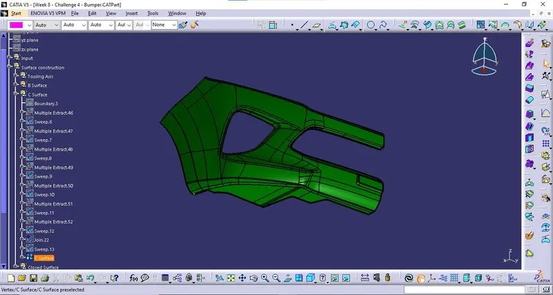
Multiple boundaries are created on the Class A Surface using Multiple Extract Command and a sweep was done with each of the boundaries as a guiding curve and Class A Surface as a reference surface at 90 degrees. Those sweeps are then joined with the Class A Surface to form C Surface.
Closed Surface:
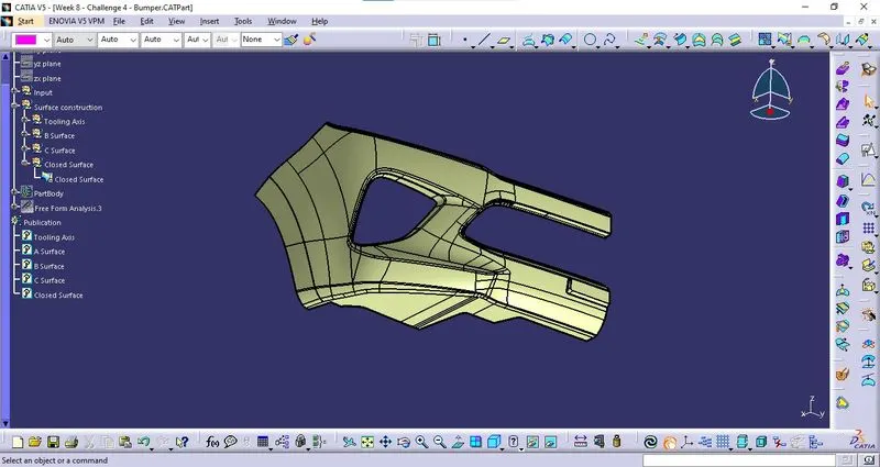
In the final stage of the surface creation, The Class A Surface and Class B Surface are trimmed together to form an appropriate closed surface.
Part Body - Bumper:
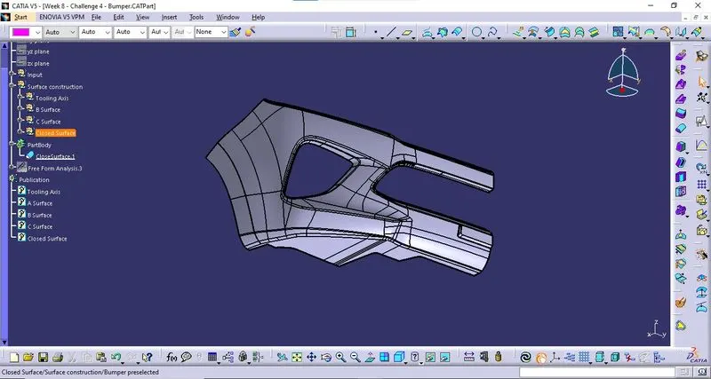
The part body is created using the close Surface command in Part Workbench with Closed Surface as the reference surface.
Isometric View:
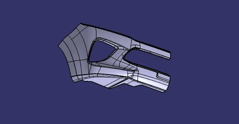
Front View:
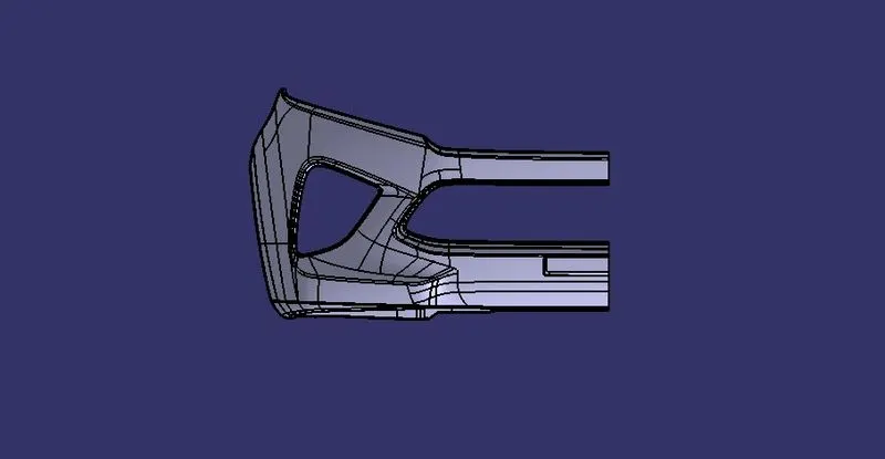
Side View:
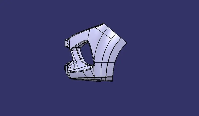
Top View:
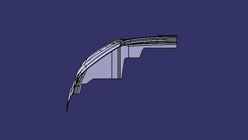
Draft analysis of the Component:
Draft analysis is done on the Component with respect to the Tooling Axis created.
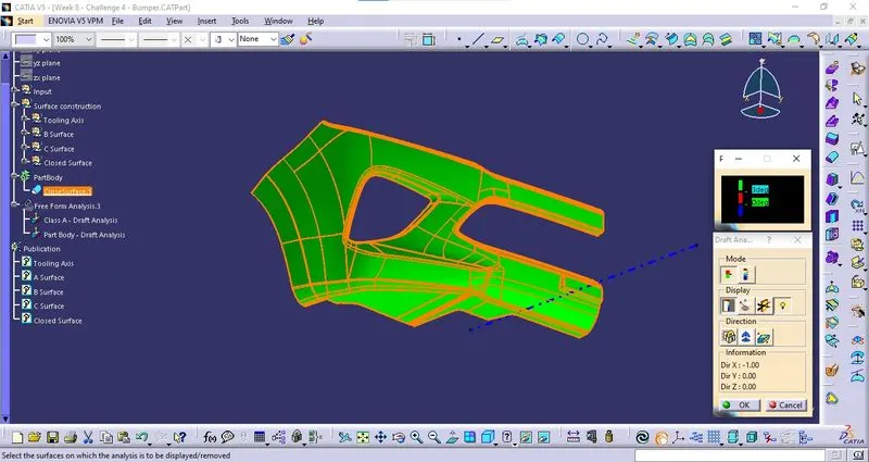
The minimum draft angle was given as 3 Degrees.
Publication:
During this process of designing the base plate, The Objects which are used frequently are published for ease of operation. Published Objects are,
- A Surface.
- Tooling Axis
- B Surface
- C Surface
- Closed Surface