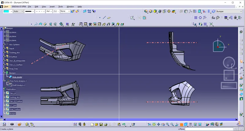
Week 8 - Challenge 4 - Bumper
Aim:
Create the Bumper Plastic component through the given Class-A surface and performing a draft analysis for the completed model.
Procedure:
- Check whether the given class A surface is joined and there is no discontinuity.
- Use join or boundary command for this if there is.
TOOLING AXIS :
- Check for a suitable tooling direction in our case , normal to x-axis is the tooling direction.
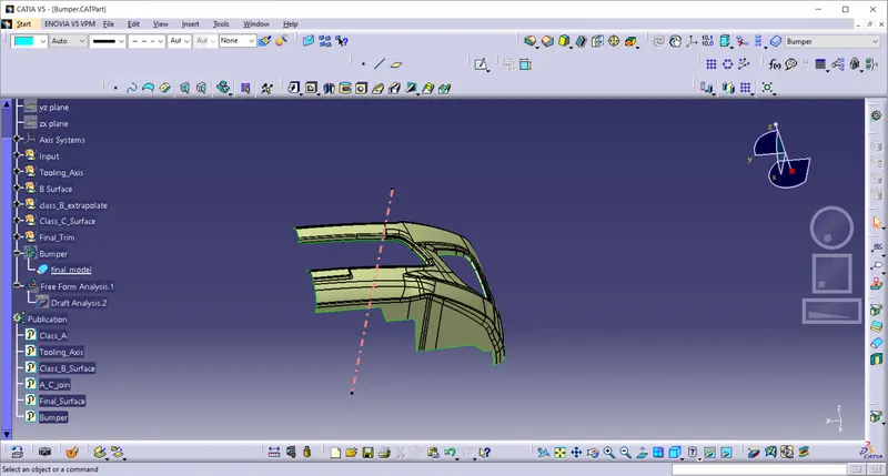
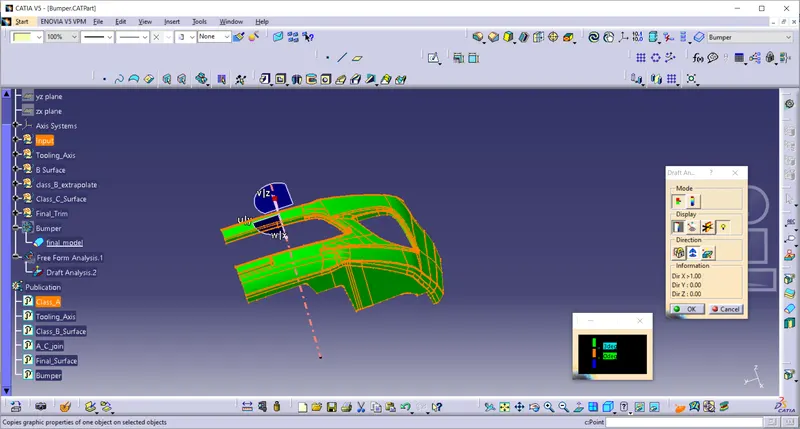
Draft Analysis on a Class A Surface
- The green surfaces will be having a draft angle of more than 3 degrees .It can clear the draft anlysis.
- The red surfaces are having draft angle more than 0 degrees and less than 3 degrees.
- The blue surfaces are having negative draft angle.
Class B Surface
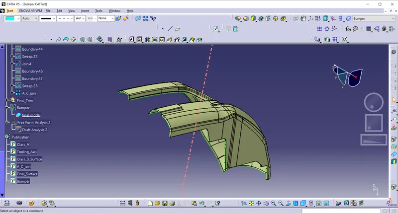
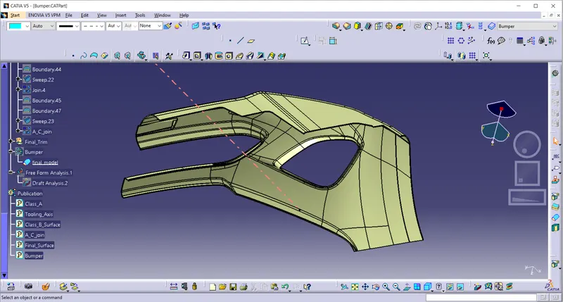
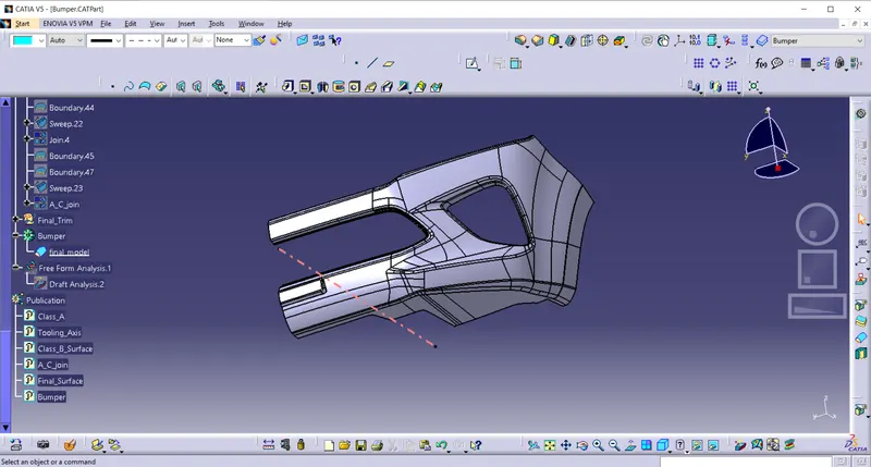
The class A surface is offseted to 3 mm and the necessary surface corrections are done.
Class C Surface:
The class C surfaces are created by sweep option and finaaly joined to the class A surface.
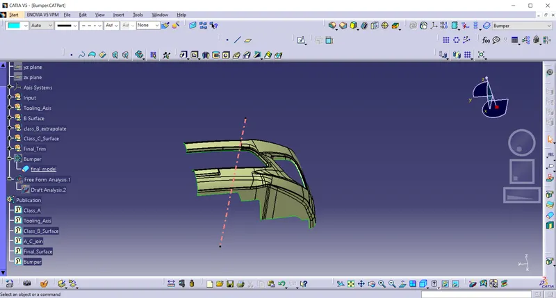
Final trim is performed to join the class A , Class B and Class C surfaces to form the closed model.
Draft Analysis of Solid Part
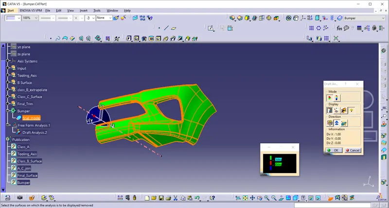
- The green surfaces are having draft angle of more than 3 degrees and they can clear the tooling direction.
- The red surfaces are having draft angle more than 0 degrees and less than 3 degrees.
- We can clearly see that the solid model surfaces are properly drafted.
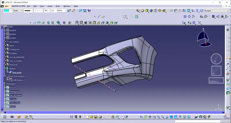
Tree Structure:
Orientation: