Week 8 - Challenge 4 - Bumper
Bumper Design
Objective
To create a Automotive Bumper using Catia V5.
Software Used
Catia V5R21
Parts in the design
In this model we have focused on the following things:
Tooling axis
Draft analysis
Class-B surface
Class-C surface
Making a solid model from surface.
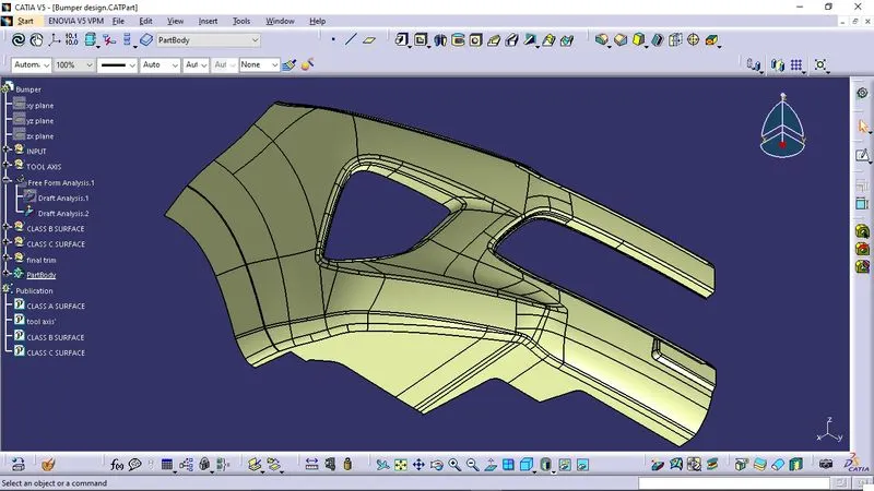
Input Class A surface
Class-A (or 'Strak') is a term used in specifically in automotive design. It describes the final production surface data for the aesthetic parts of the car.
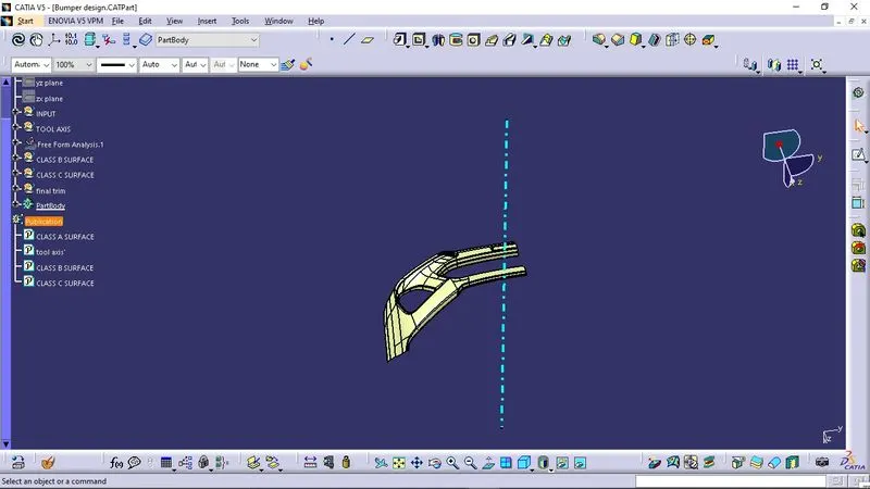
Tooling Axis
Tooling axis or tooling direction is main consideration for plastic part and mold parts because it defines movement of mold part and possibility of plastic part to come-out from mold part (Core and Cavity). In Molding machine arrangement is given to open the mold along a direction which is known as Tooling Direction. The mold is built from two separate halves (Core and Cavity) and tooling direction basically define the direction of mold pulls apart. Tooling direction is known as primary direction.
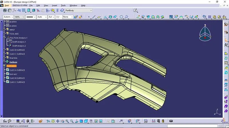
Class B Surface Creation
The surface which is back side of Class A surface is called Class B Surface. Mostly it not visible. It is created with the help of Class A surface with some distance (thickness) like 2mm, 3mm etc.
Final Output
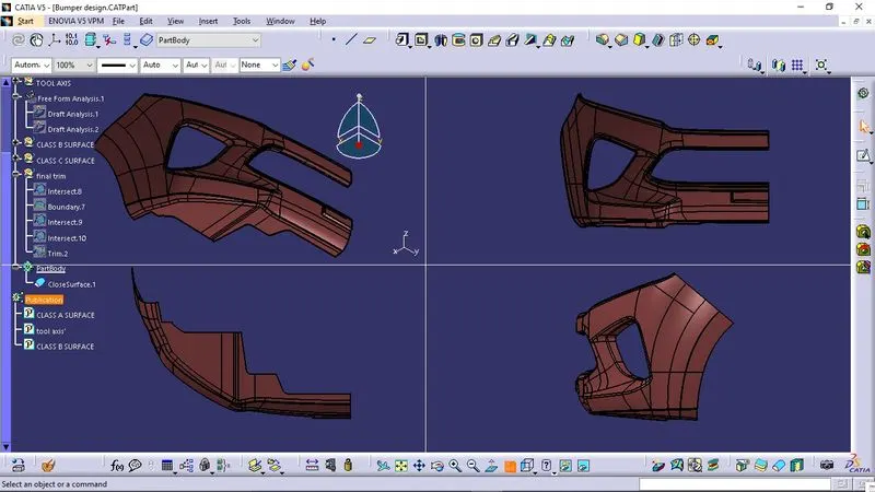
Draft Analysis
The Draft Analysis allows the user to easily analyze a part for proper draft angle. A Draft Angle describes the amount of taper for molded or cast parts perpendicular to the parting line. Draft Analysis is applicable for 3D part models. To create a draft analysis for any 3D part file, the user needs to select part/surface select the pull direction. You can change the pull direction.
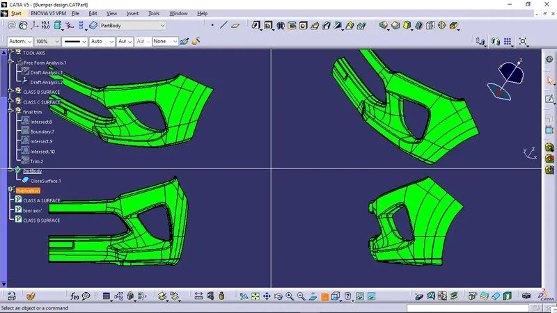
Conclusion
The bumper design have been concluded.