Week 8 - Challenge 4 - Bumper
Tree Structure
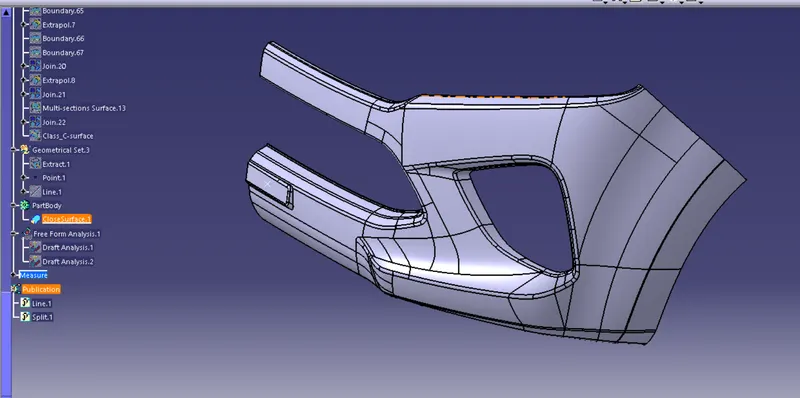
- Proper Tree Structure
- Geometrical sets have a proper name based on the sketches present inside of it
- All the sketches was created under the Geometrical set
- Used the Close Surface feature to make a solid body from the surface.
- Publications: Used the publication option and publish the below
- Tooling Axis
- Class A, B, and C surface
Tooling Axis creation and Draft Analysis on a given Class-A Surface of Bumper
Objective:
The Objective of the project is to do Draft Analysis by Creating the tooling direction for given Class A Surface. and Thickness of the component is 3 mm
Introduction:
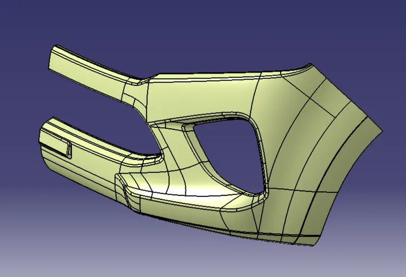
The Draft Analysis command enables you to detect if the part you drafted will be easily removed. This type of analysis is performed based on colour ranges identifying zones on the analyzed element where the deviation from the draft direction at any point, corresponds to specified values.
Tooling direction is the main consideration for plastic part and mould parts because it defines the movement of the mould part and the possibility of the plastic part coming out from the mould part (Core and Cavity).
Tooling Direction:
- Tooling direction is known as primary direction. In Molding, machine arrangement is given to open the mould along a direction which is known as Tooling Direction. In other words. The mould is built from two separate halves (Core and Cavity) and tooling direction basically defines the direction of mould pulls apart.
Procedure for Creating Tooling Axis:
- First, the given styling surface was imported into CATIA and checked for irregularities by using Join, Boundary and Disassemble option.
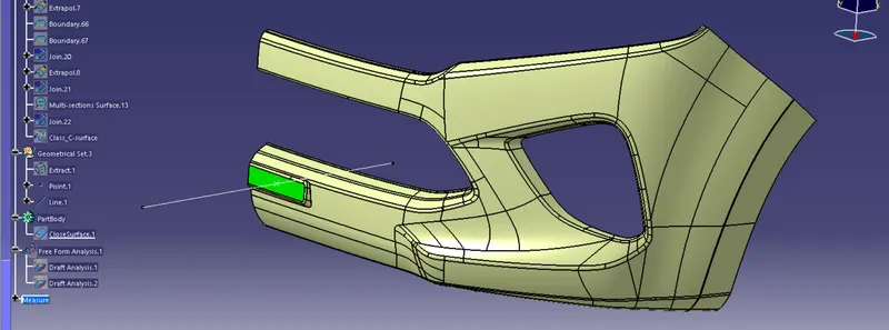
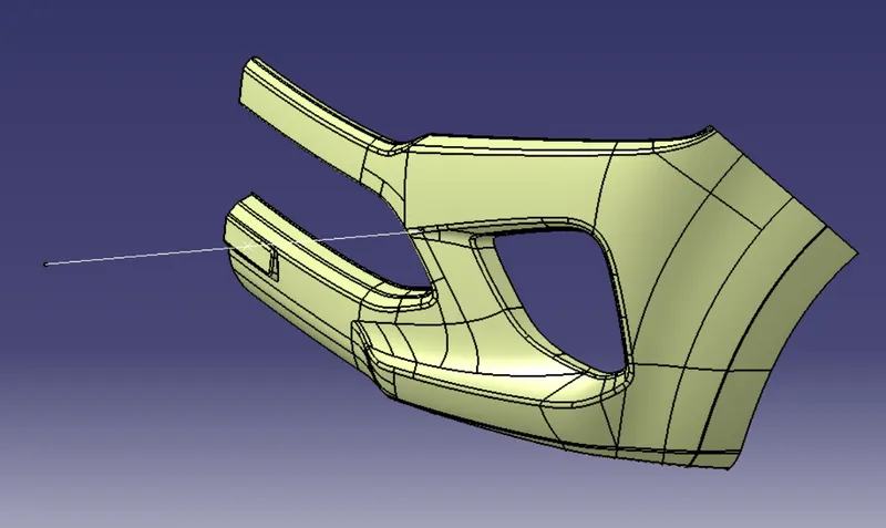
- Then Make a point on the surface and create line for Tooling Axis. Here i did't used bisecting lines.
Publications:
The tooling axis and class-A surface were published for further easy reference, from Tools – Publications.
Performing Draft Analysis:
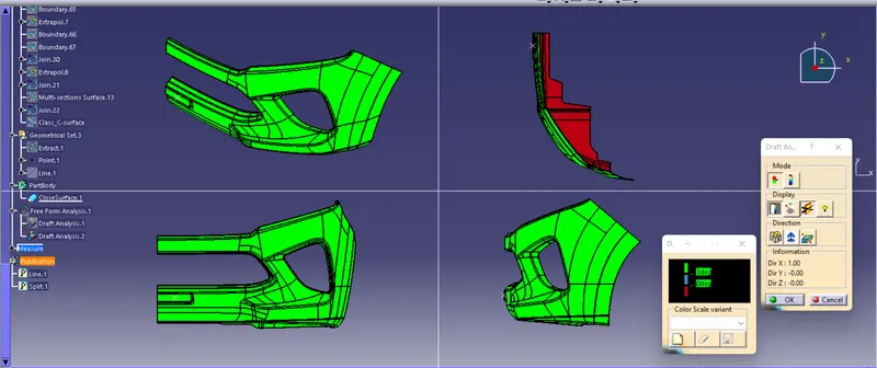
- For plastic parts, the nominal angle value for draft analysis is 3 degree but even a 0.5-degree angle can be created for sub-assemblies like ribs and slots. (For Sheet Metal 7 degree angle is the nominal value)
- Insert – Analysis – Feature Draft Analysis
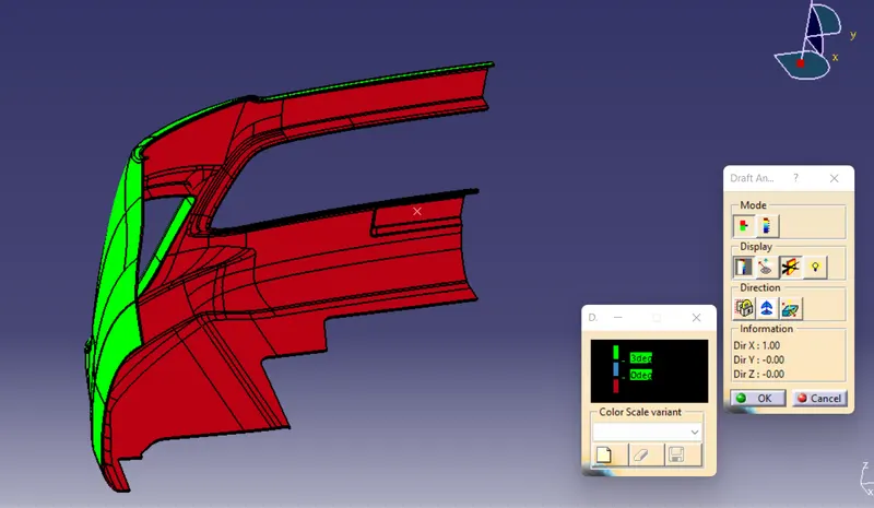
- Draft analysis was carried out by pulling the compass to the tooling axis and an inverse draft axis was carried out if required.
- After setting the compass over the tooling axis the compass must be locked to a specific direction.
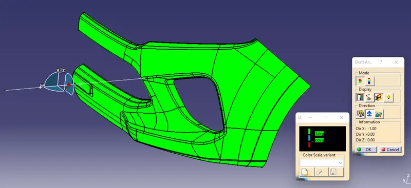
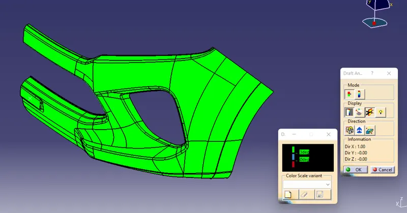
- If the surface was in green then the model passes or else further operations need to be carried out.
- By using full analysis mode detailed analysis can be carried out for complicated assemblies.
- By using the analysis under the running point complicated parts and surface were checked in detail.
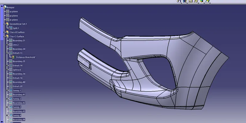
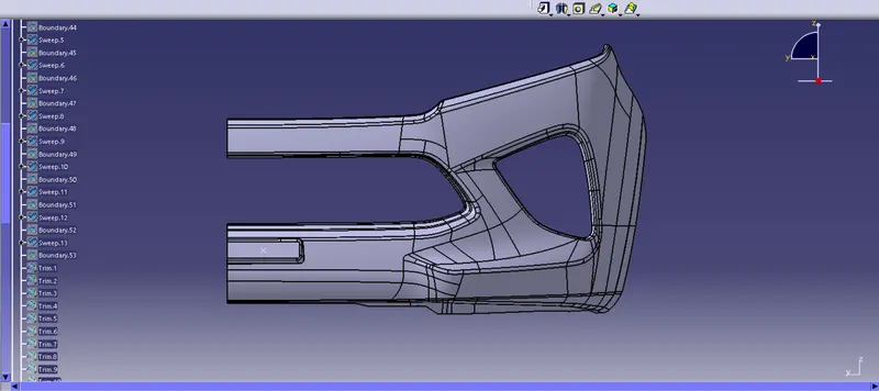
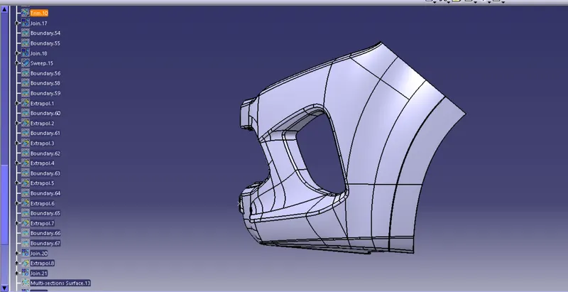
Feature Tree:
Conclusion:
The Draft Analysis for Bumper has done. it was carried out by creating the perfect tooling direction.