Week 8 - Challenge 4 - Bumper
- Week 8 - Challenge 4 - Bumper
- OBJECTIVE:-
- Create the Bumper Plastic component through the given Class-A surface.
- To begin with, the tooling axis for the given Class-A Surface should be created to meet the requirements of the draft angle
- To perform the Draft analysis on the model.
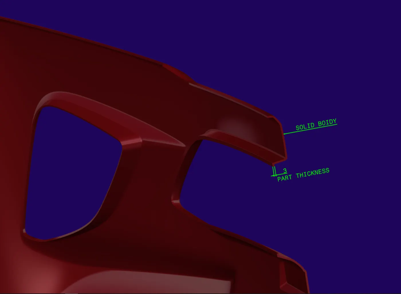
- Take the Thickness of the component to be 3 mm
- ------------------------------------------------------------------------------
- Different views of the MODEL:-
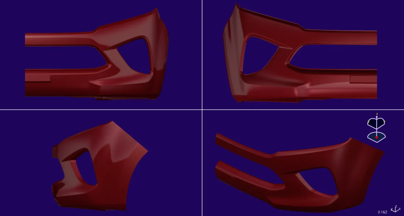
- ------------------------------------------------------------------------------
- Consideration while designing the model:-
-
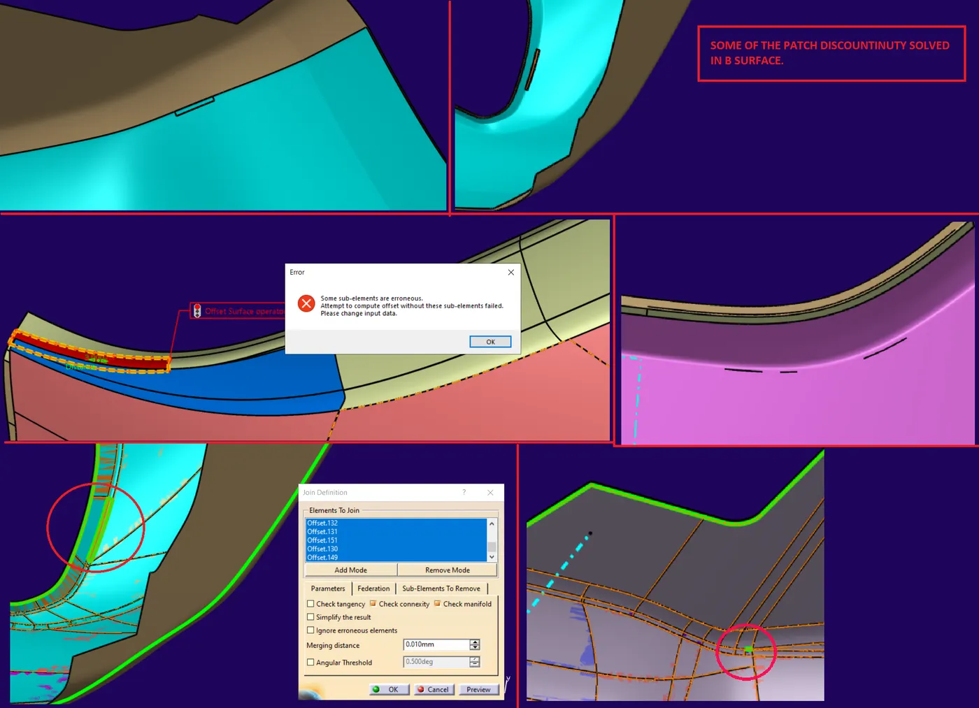
The distance between each point of the edges of two neighbouring patches must comply with the following limits:
-
For class A: no more than 10 µm = 0.01 mm
-
For class B: no more than 20 µm.= 0.02 mm
-
For class C: no more than 50 µm.= 0.05 mm
-
The angle between the tangents to the surface on the edges of two neighbouring patches must comply with the following limits:
-
For class A: no more than 6’ = (0.1◦).
-
For class B: no more than 12’ = (0.2◦).
-
For class C: no more than 30’ = (0.5◦).
-
(Note:- ( ’) _means minute:- (ex. conversion of minute to degree: - 6’ = 6/60 = 0.1 degree)
-
------------------------------------------------------------------------------
- Expanded tree view with model construction steps:-
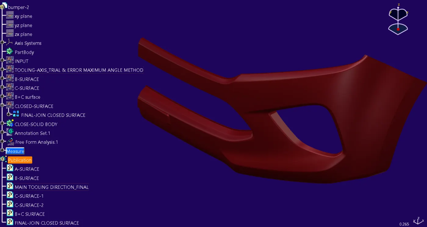
- CLASS-A SURFACE INPUT AND BOUNDARY CHECK
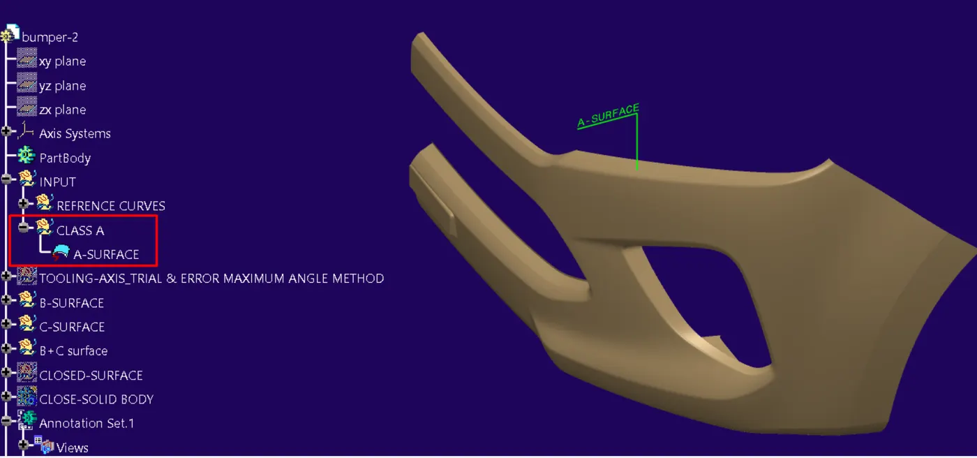
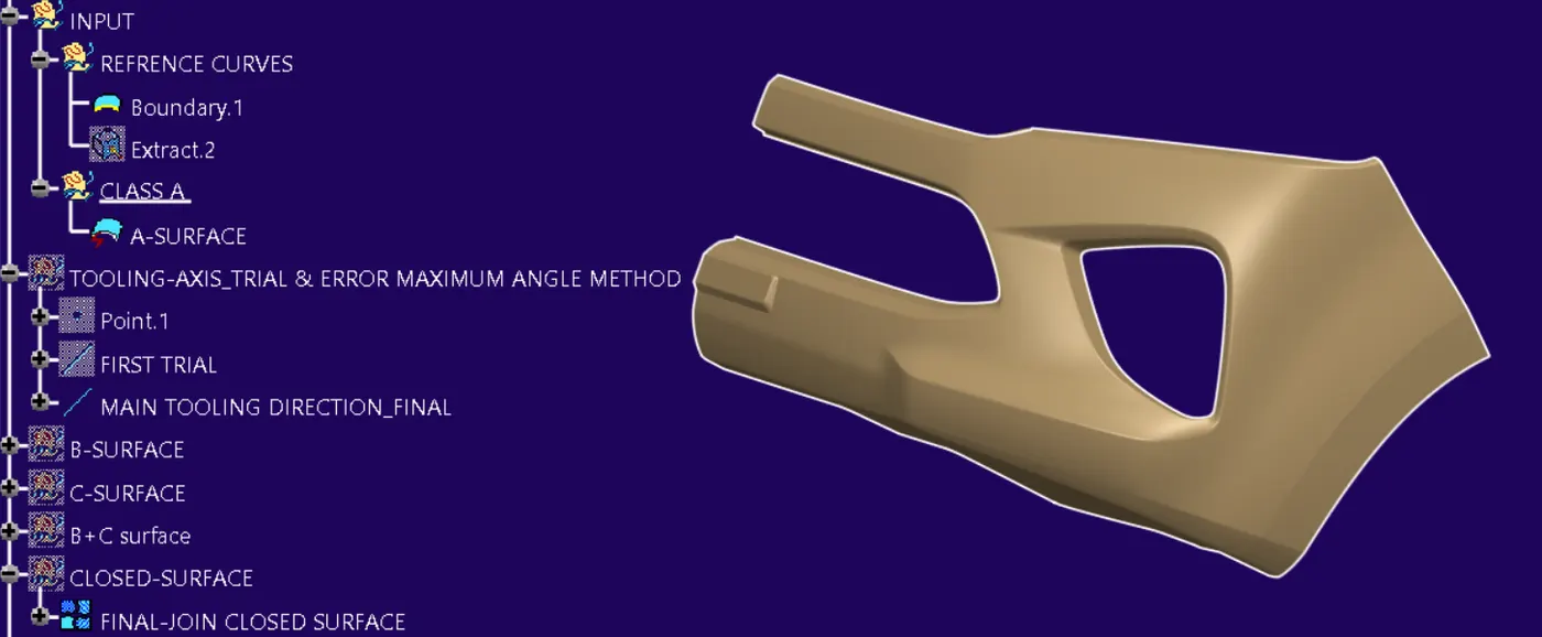
-
------------------------------------------------------------------------------
- TOOLING AXIS.
- DEFINITION:-
- Tooling axis:- “ main tool axis” is the axis that defines the mould opening direction.
- The tooling axis must be created on a feature like a hole, slot, cut-out, flat surface, or continuous surface of a Class A Surface.
- The tooling axis justifies the angle sector of the side wall draft ”C-surface”, that is the positive angle of the C surface in the direction of the ejection, “i.e. it creates a relation of the component from mold opening to the ejection of part”.
- The tooling axis must be created in such a manner that gives the ejection clearance and mold opening clearance such no undercut will come in the way during ejection and mold opening,
- it also provides the reference axis to the slider axis or angled pin axis, which is used for the undercut inserts, (known as the undercut at an angle of tool axis),
- While designing mould tools, it is practised that the ejection pins - straight action form pins must be constrained to move parallel to the tooling axis.
- Straight action form pin these pins are ejection pins used to release the Internal undercuts”,
- similarly, sliders are used to remove the external undercut.
- METHODOLOGY:-
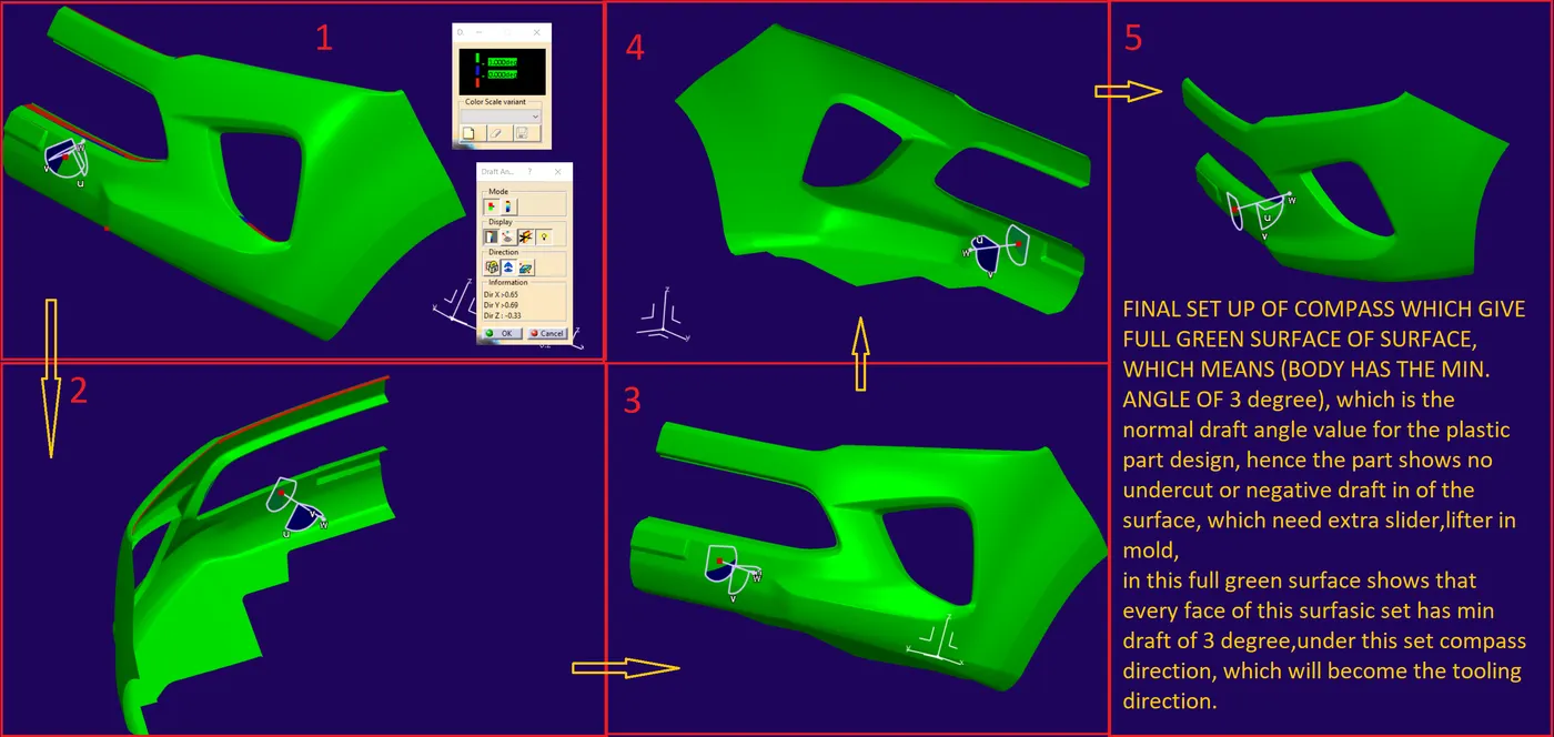
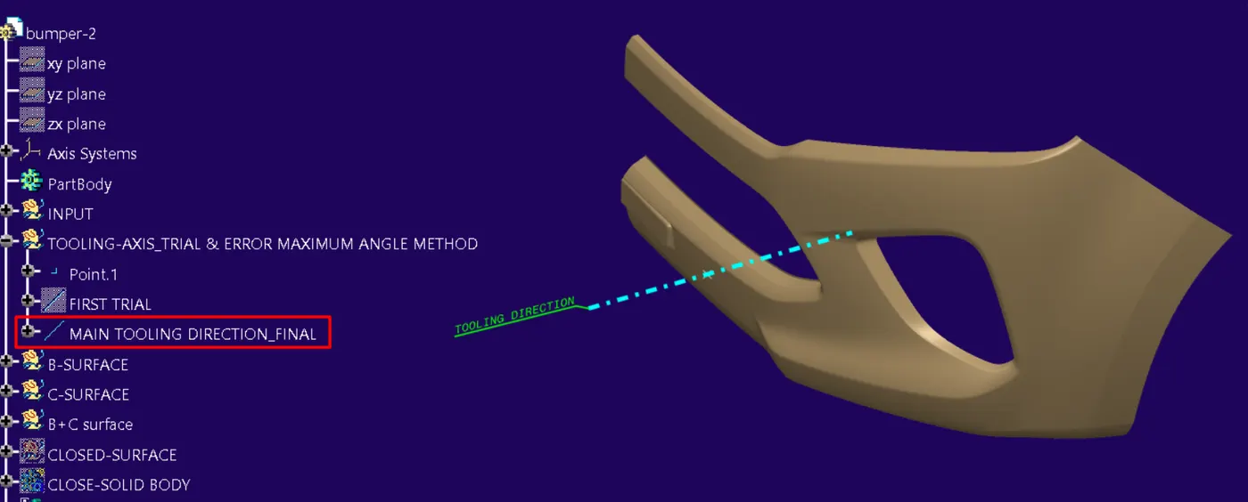
- The method used to find tooling direction in this model is " TRAIL & ERROR MAXIMUM ANGLE METHOD"
- In this method, tooling direction is found with the help of draft analysis.
- method:-
- 1. set A-SURFACE, In such a view from where every surface face and feature is almost visible.
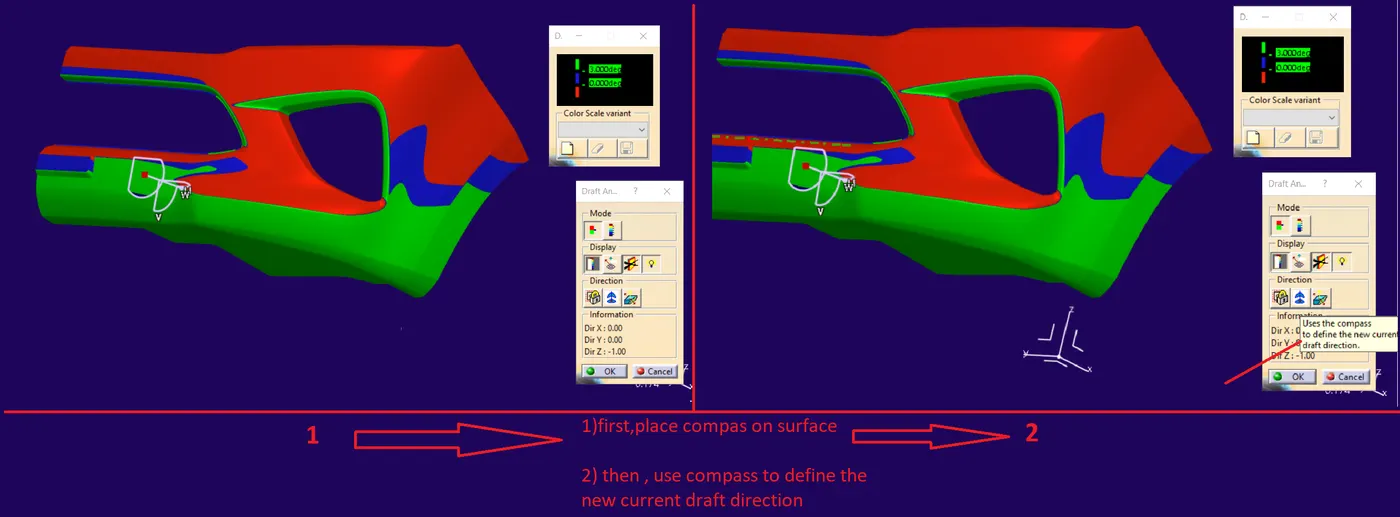
- 2. Place the compass on the A surface."AS SHOWN IN BELOW IMAGE"
- 3. SET COMPASS DIRECTION " AS SHOWN IN THE BELOW IMAGE"
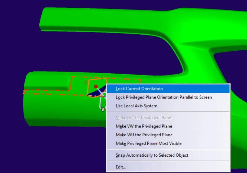
- 4. LOCK SET COMPASS DIRECTION " AS SHOWN IN THE BELOW IMAGE"
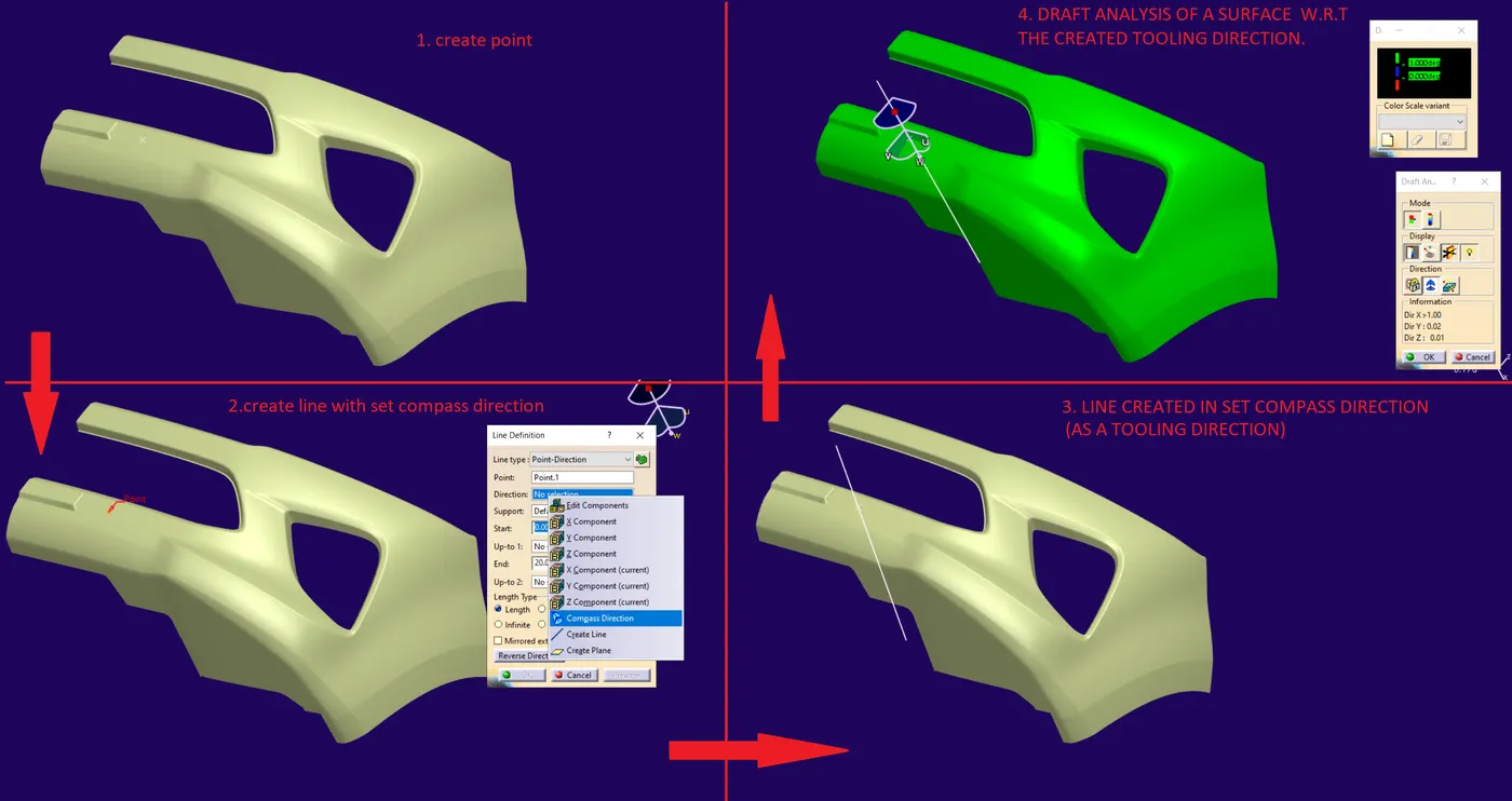
- 5. CREATE TOOLING DIRECTION LINE AND DRAFT ANALYSIS " AS SHOWN IN THE BELOW IMAGE"
- 6. TOOLING DIRECTION.
- ------------------------------------------------------------------------------
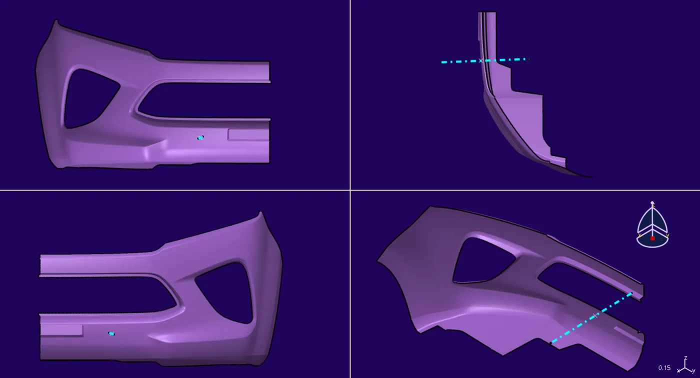
- B-SURFACE "DIFFERENT VIEWS"
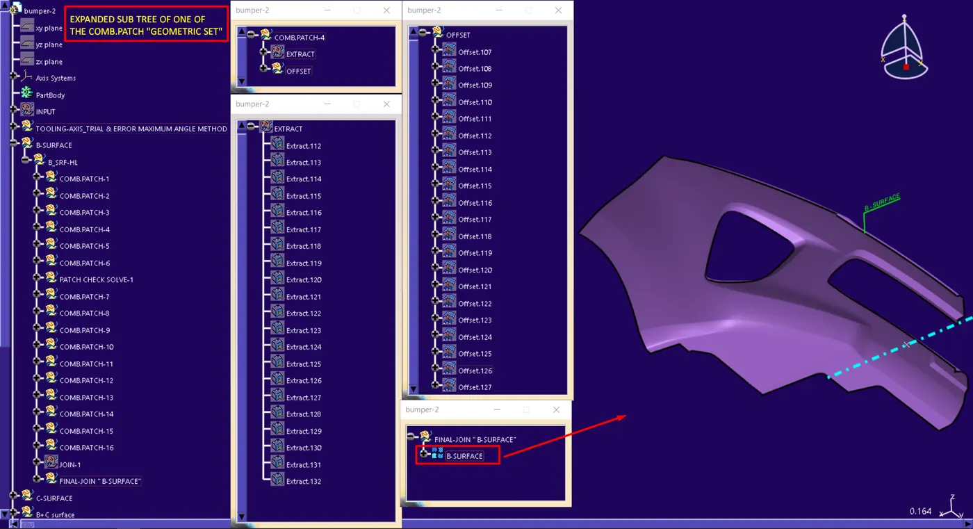
- B-SURFACE WITH EXPANDED TREE VIEW
- SOME OF THE DISCONTINUOUS PATCHES SOLVED IN B SURFACES " FIG SHOWS SOME OF THE PATCHES DISCONTINUITY ERRORS"
- FINAL B-SURFACE
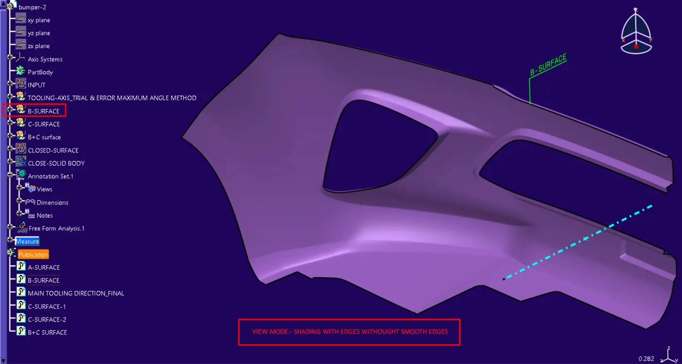
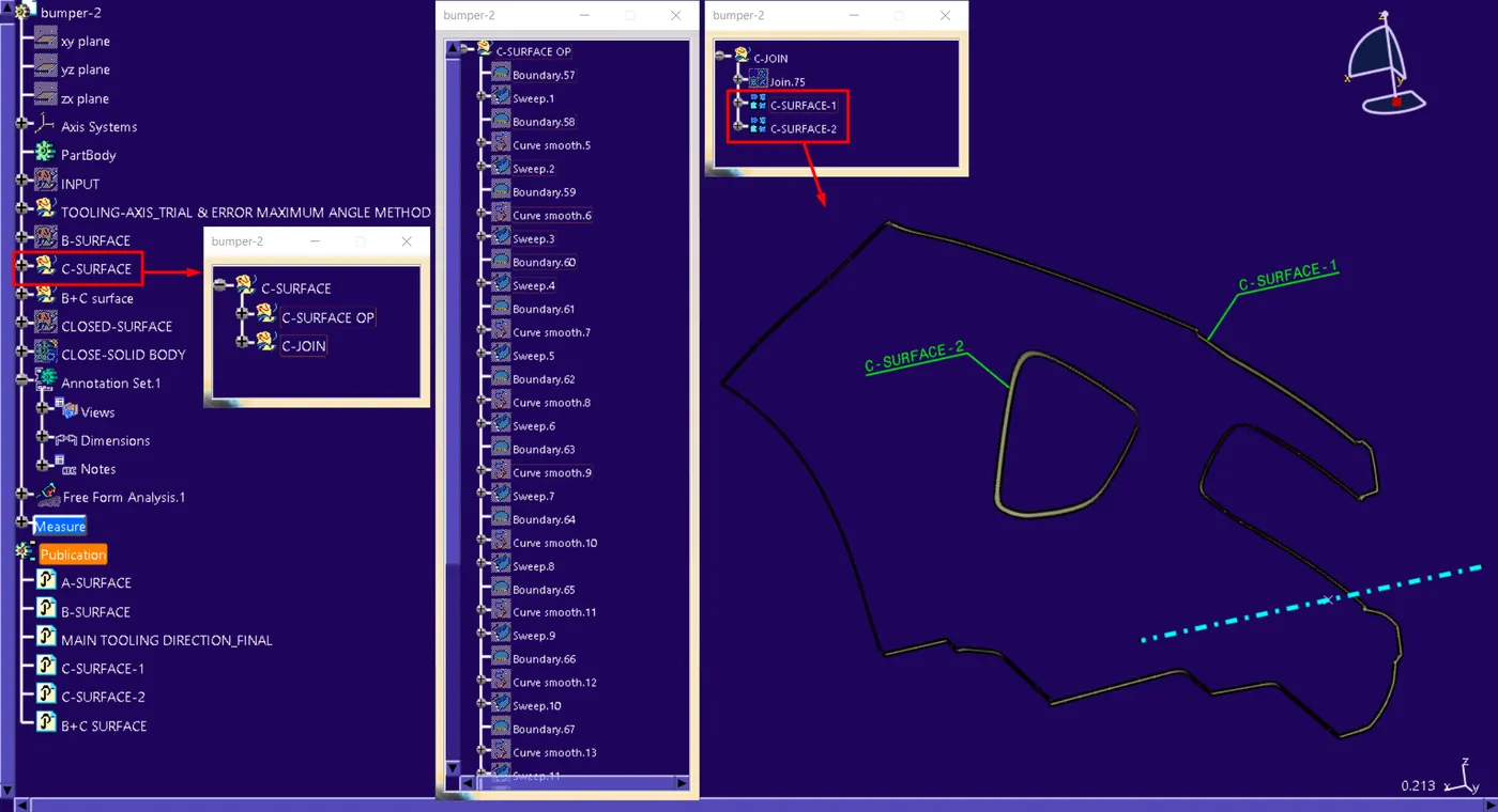
- C-SURFACE
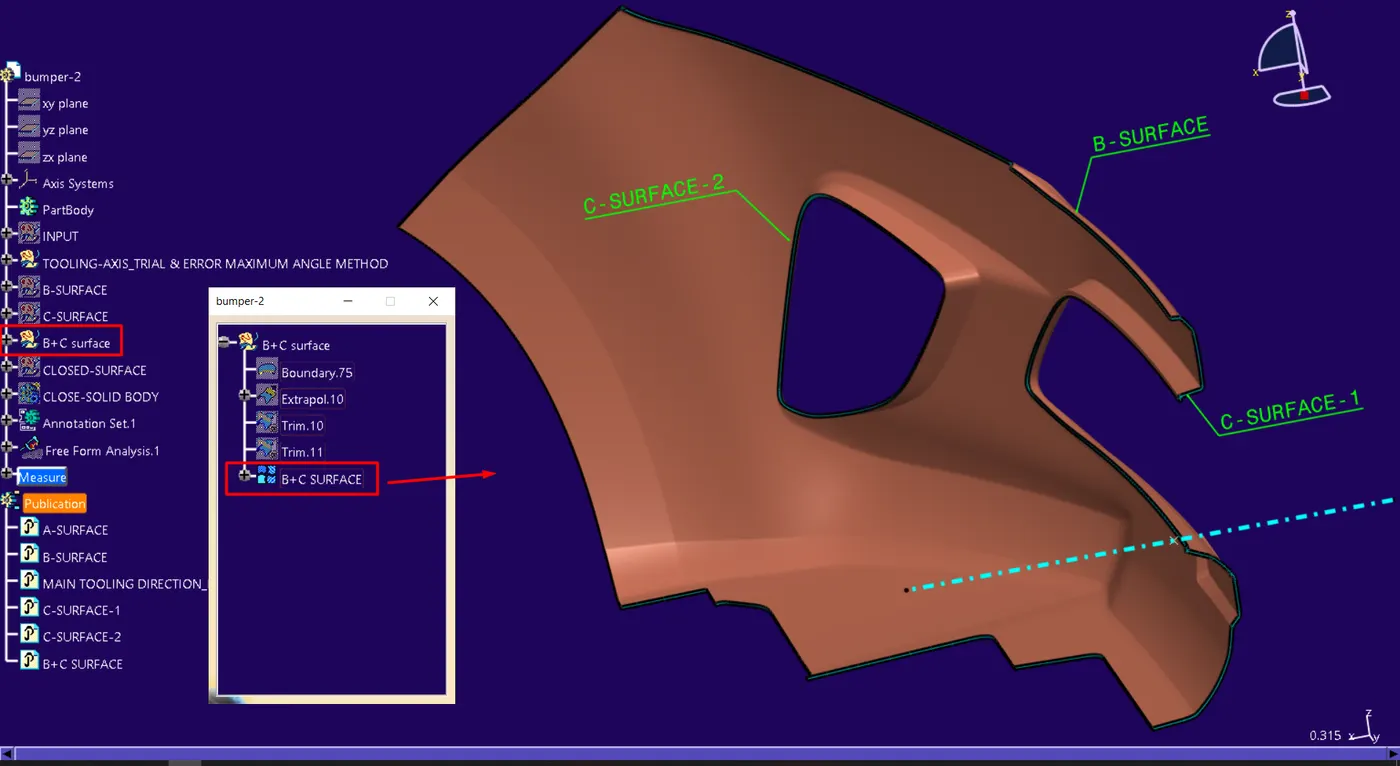
- B+C SURFACE
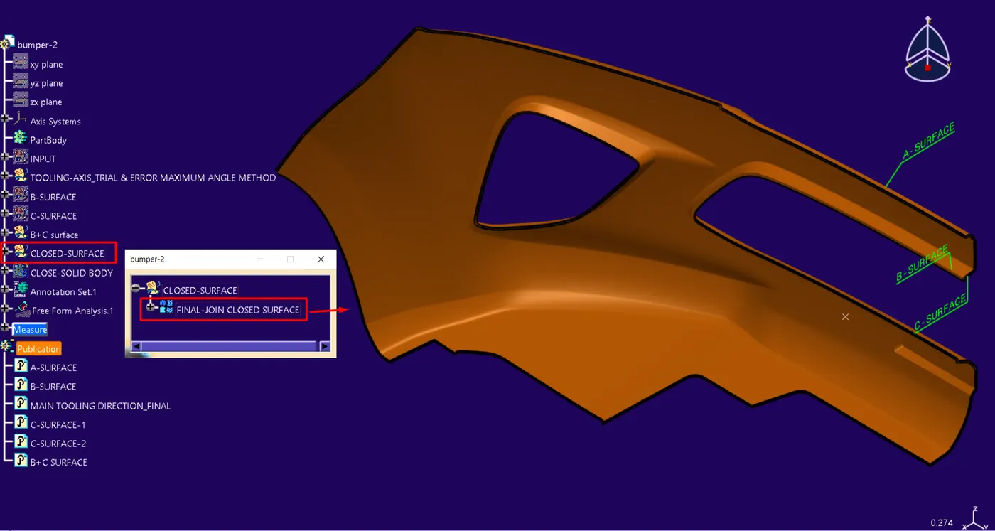
- CLOSED-SURFACE
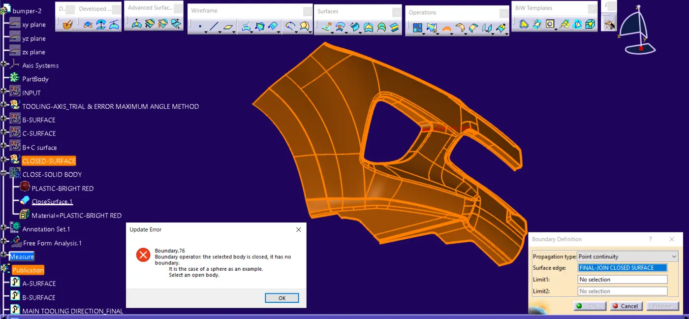
- CLOSED-SURFACE-BOUNDARY CHECK
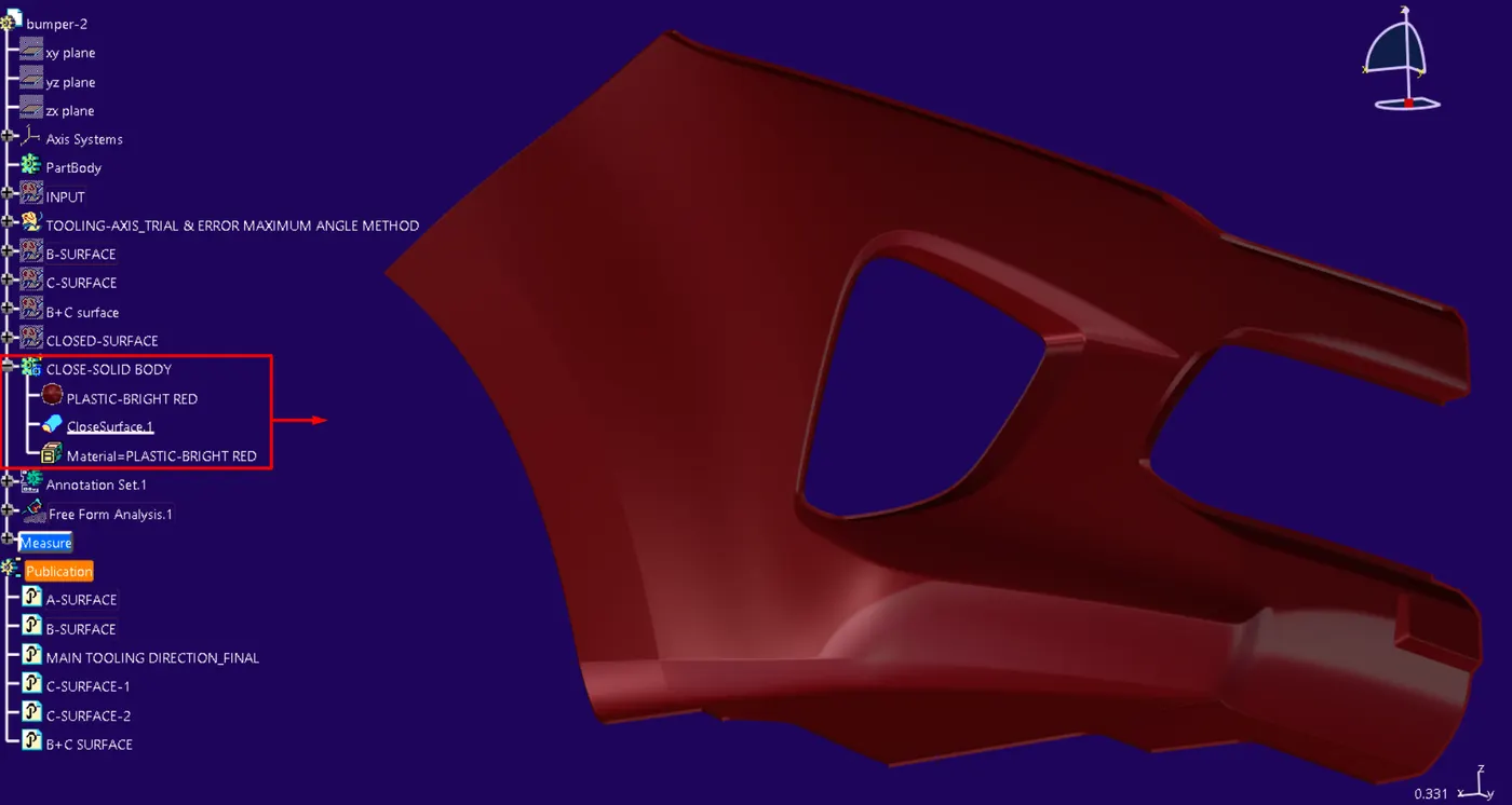
- SOLID BODY:- from a closed surface
- SOLID-BODY THICKNESS
- ------------------------------------------------------------------------------
- DRAFT ANALYSIS:-
- DEFINITION:-
- The Draft Analysis enables you to detect if the part drafted will be easily removed “EJECTED”
- The analysis is performed based on colour ranges identifying zones on the analyzed element where the deviation from the draft direction at any point, corresponds to specified values”
- DRAFT ANALYSIS COMPASS:-Terminology
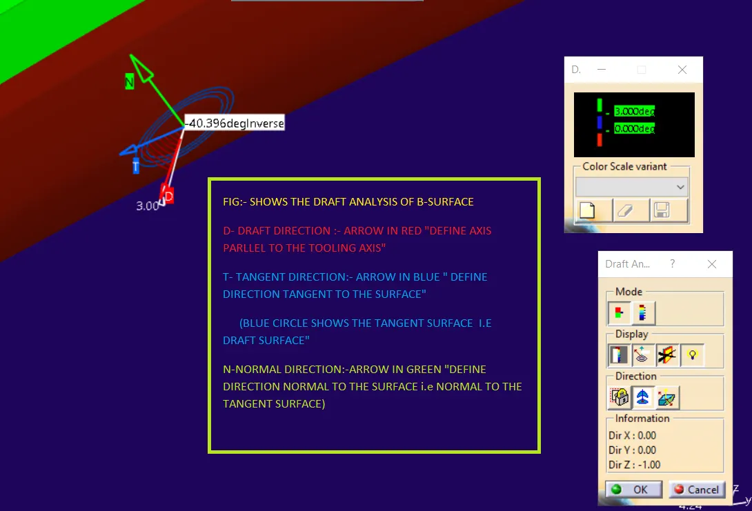
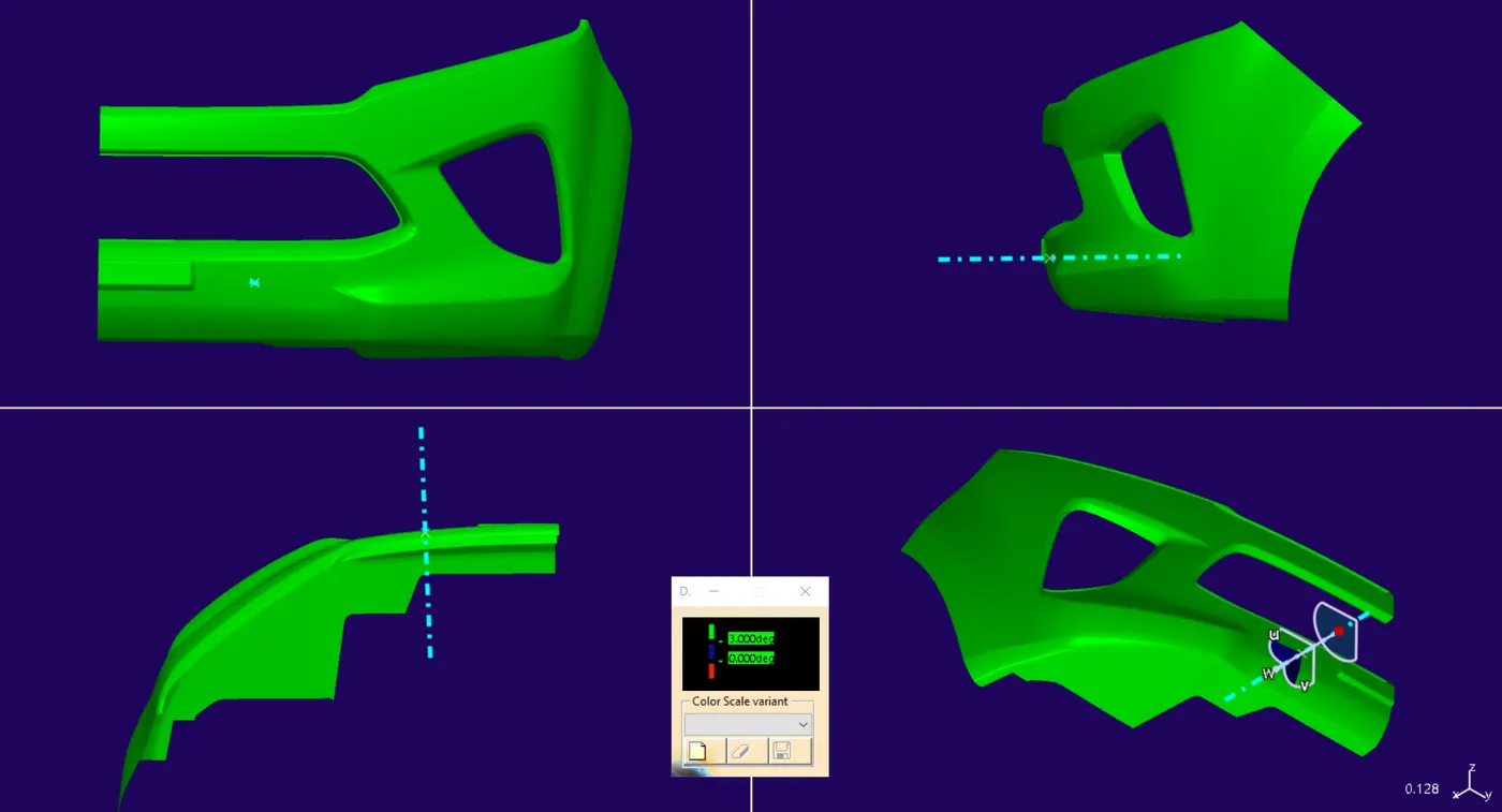
- DRAFT ANALYSIS OF CLASS A SURFACE.
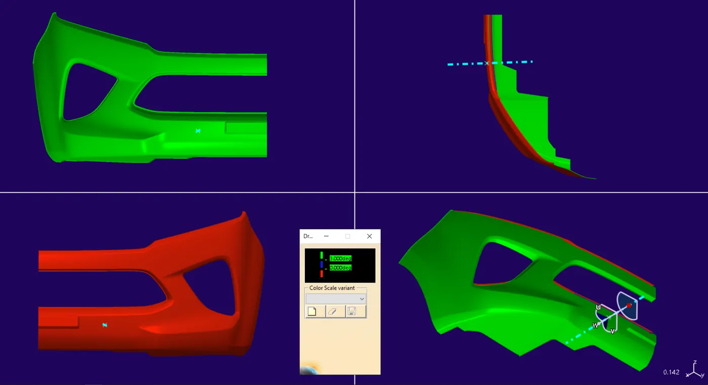
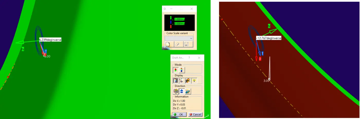
- DRAFT ANALYSIS OF SOLID BODY.
- ------------------------------------------------------------------------------
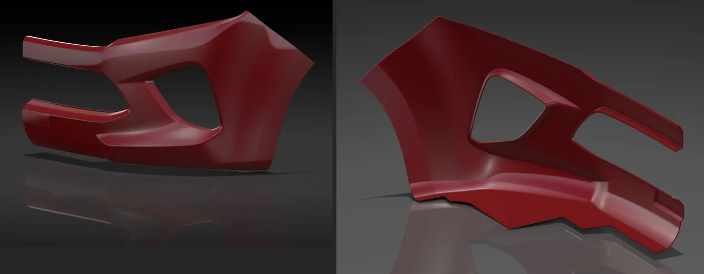
- RENDERED VIEWS OF THE MODEL:-
- SECTION VIEW
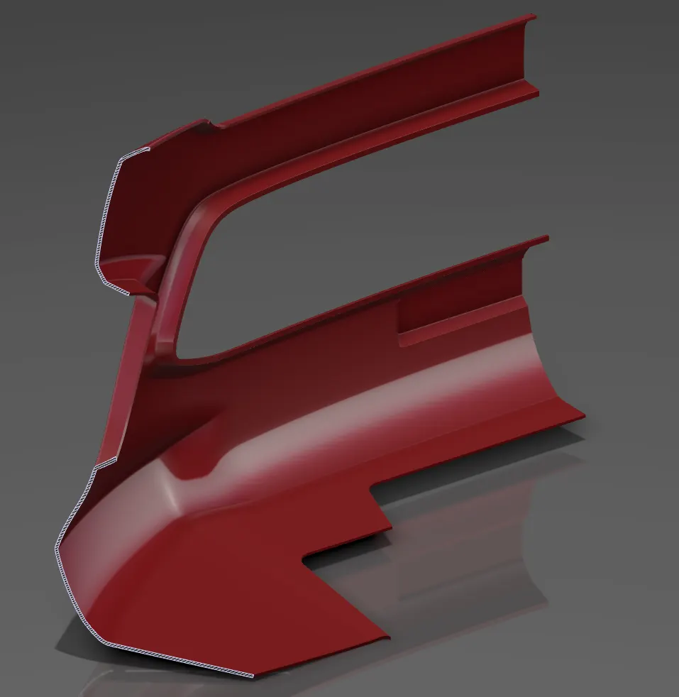
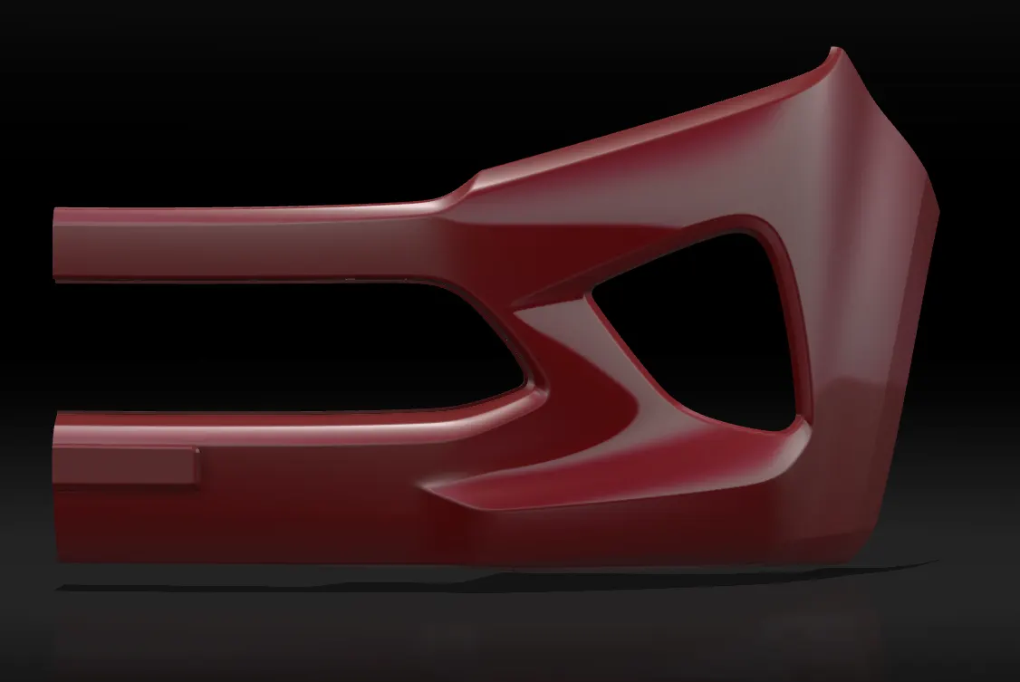
- ---------------------------------------END-----------------------------------