Week 8 - Challenge 4 - Bumper
CREATION OF BUMPER BODY FROM A-SURFACE
AIM :
To create a body of Bumper from the input given which was the A-surface of a Bumper. The created body should be a closed solid volume which should be feasible for manufacturing and Tooling. The draft angle and draft analysis of the component should be done.
In model, proper tree structure to be maintained and publications of Tooling axis,A,B and C surfaces to be done
NPUT GIVEN:
-
A-Surface
-
Thickness of component is 3.00mm
- Draft angle is 3 degrees.
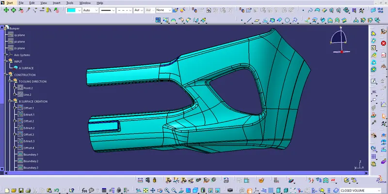
CHECKING THE INPUT - A SURFACE:
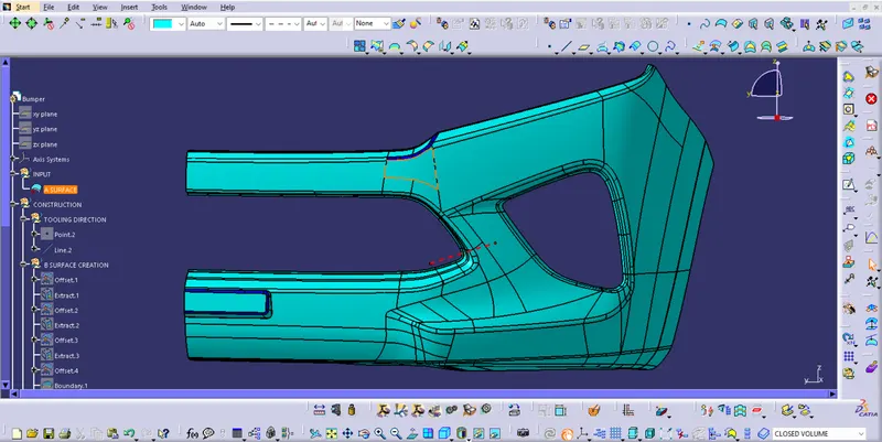
CREATION OF TOOLING AXIS:
The opening and closure of the mold cavity and core during the component-making process are represented by the tooling axis. The best tooling direction should be taken into account by a plastic product designer in order to drastically reduce component costs.
The method is chosen to create the bumper's tooling axis-
- 1. Verify which tooling direction will work best on the given surface.
- 2. Cross-checking all three dimensions allows us to identify the ideal tooling direction.
- Here, we learn that the x-axis direction is the optimal tooling direction for the pumper class-A surface.
- I first extract a surface and then make a midpoint on that surface in order to construct the tooling axis. At that point, an axis system was introduced.
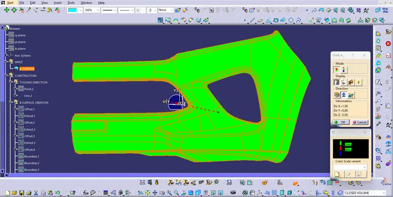
Draft analysis on the finished component:
Green color denotes- Draft angle 3 degrees and above
Red denotes- 0 degree
Blue denotes- Less than 0 degree
B-SURFACE CREATION OF :
The A-surface is offsetted by 3.00mm as it is the thickness required.
The offset surface is the B-surface but had some issues like in some areas shown in below images.
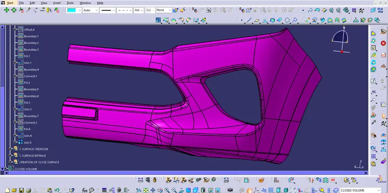
The Areas where the B-surface has issues are corrected by closing them using commands like Multi section,Sweep,Offset and extract.
Finally all the created surfaces are trimmed or joined together with offset surfaces done earlier. This created a single single surface which will act as the final B-surface. (See Image 7)
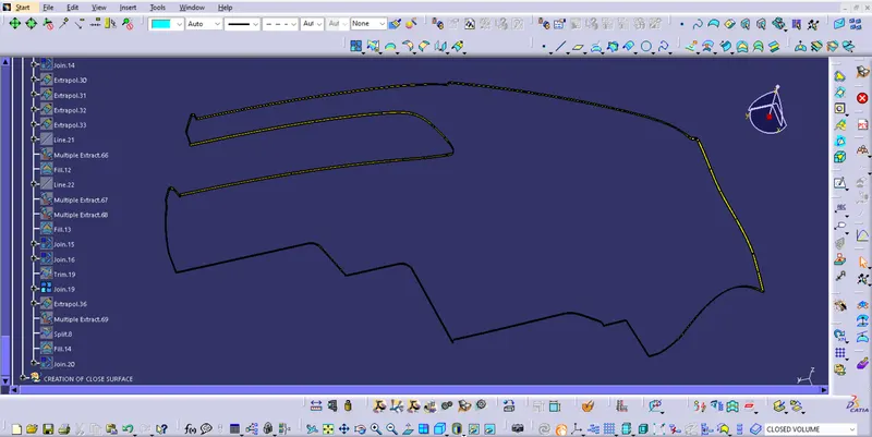
B surface created is checked for any gaps or errors by creating a complete boundary as shown below .
C-SURFACE CREATION :
CREATION OF CLOSED BODY :
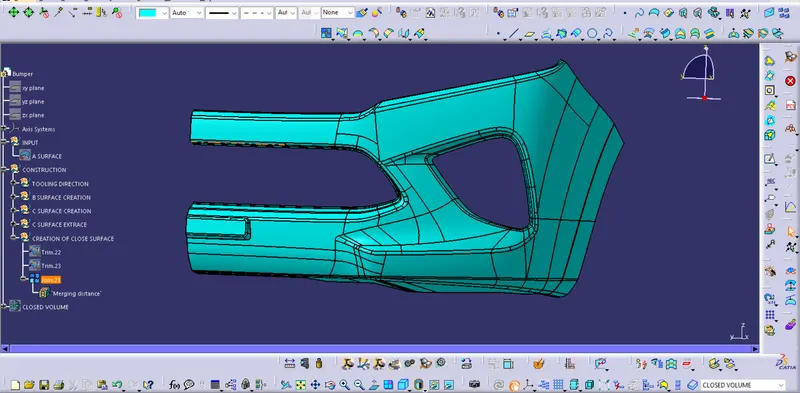
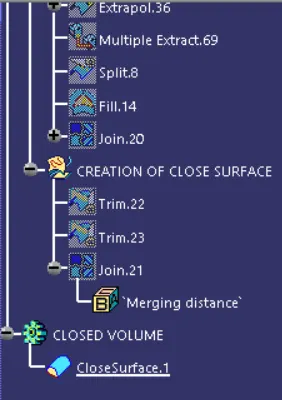
All the surfaces (A,B,C) are joined together to form a closed body.
Boundary is selected and the body is picked. Since an error popped up it can be understood that all surfaces are joined with each other to form a proper closed surface body.(See Image 10)
Finally in part design workbench, using close volume it is changed to a solid body.
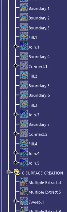
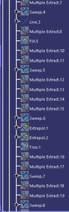
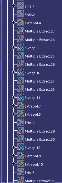
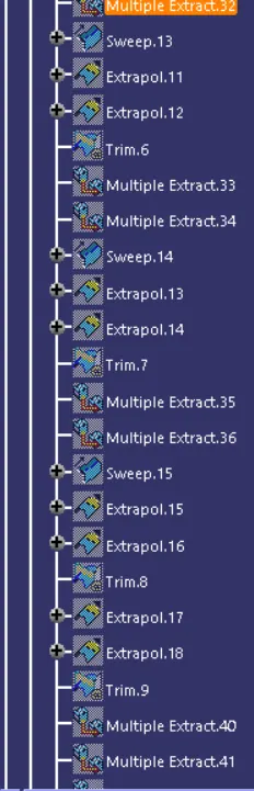
MODEL TREE:
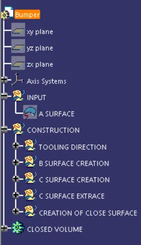
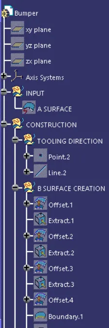
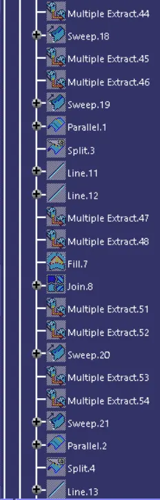
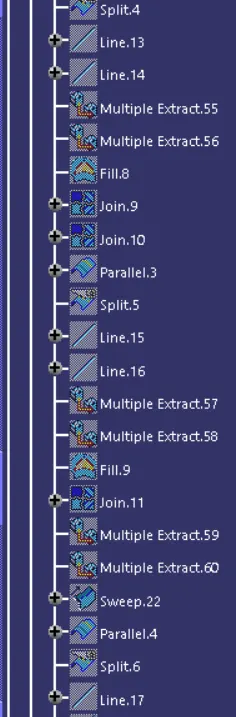
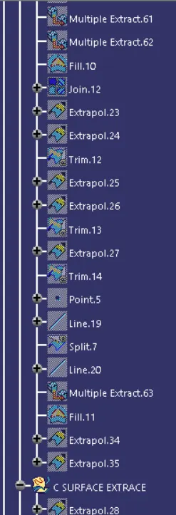
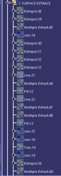
The model tree created shows that all the geometrical sets are named for clarity.
The publications of Tooling axis, surfaces of A,B and C surfaces are done.
Also the closed surface body and Volume is published.
Conclusion:
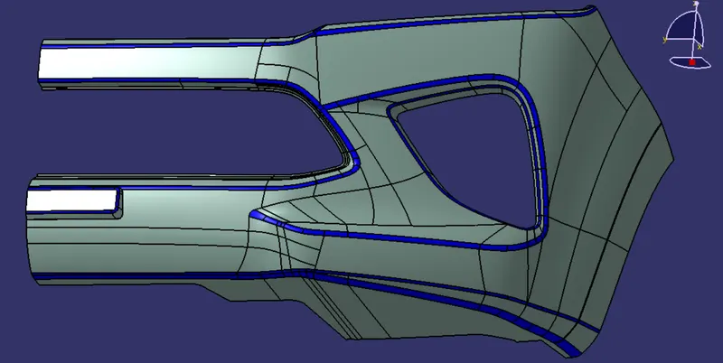
The Draft analysis of the component showed that the component is feasible to be molded without any issues.
Thus it satisfies all design and manufacturing criterias needed for a proper part.
This concludes the report of Design of Bumper Body.