Week 8 - Challenge 4 - Bumper
WEEK 8 - CHALLENGE 4 - BUMPER
AIM:
Create the Bumper Plastic component through the given Class-A surface. To begin with, the tooling axis for the given Class-A Surface should be created meeting the requirements of the draft angle and at the end perform the Draft analysis on the model.
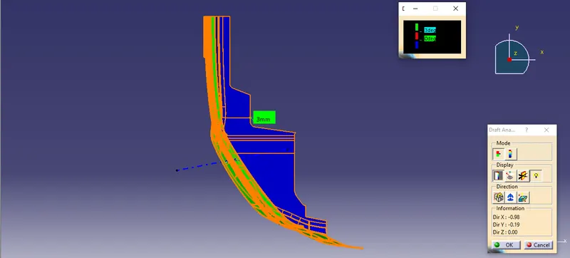
Take the Thickness of the component to be 3 mm
CREATION OF THE TOOLING AXIS
TOOLING AXIS
It is nothing but the direction in which the mold opens and closes the draft angle needed to be provided by considering this tooling axis.
We can create a tooling axis by using the bisecting method.
BISECTING METHOD
This method is used for the generation of the tooling axis for that purpose first we need to decide the direction of molding and then we create one dummy tooling axis for the reference to the purpose.
In this method, we select the surfaces which can create problems and take intersections with respective planes in the x and y-direction. By using these intersection curves we draw two lines and then draw a bisecting line from these two lines in the x-direction and y-direction.
After completing this we need to draw a final line bisecting these two tooling axis in the X and Y directions to get our final output.
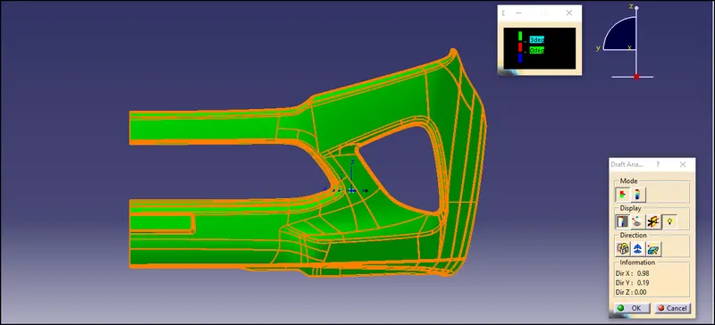
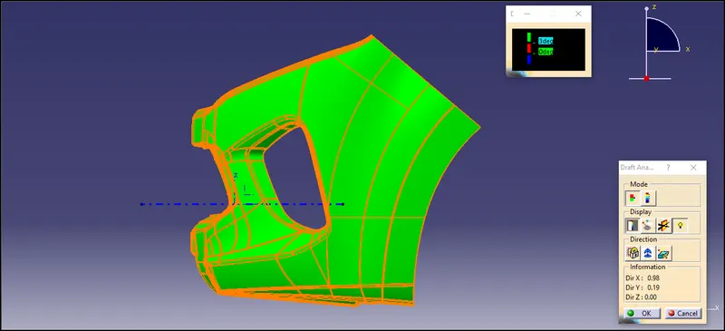
DRAFT ANALYSIS FOR THE CLASS-A SURFACE
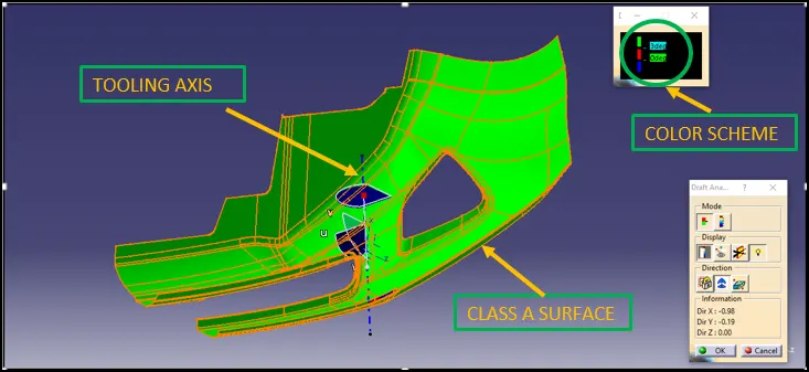
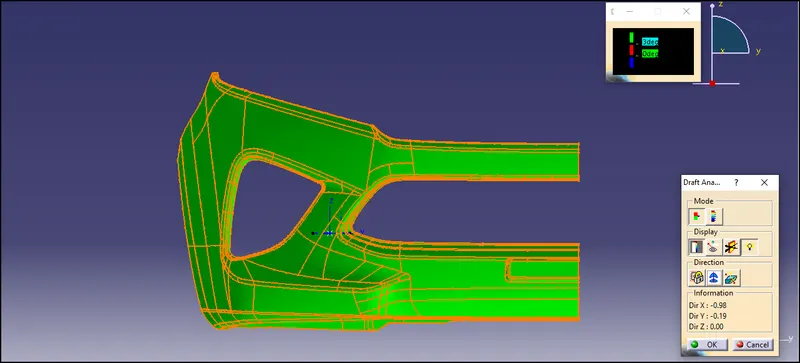
In the above images, the draft analysis of the Class A surface has shown the draft angle should be more than 3 degrees and this can be clearly observed from the above images that the surfaces have an angle of more than 3 degrees.
This means we can manufacture the part with ease.
DRAFT ANALYSIS FOR THE SOLID BODY.
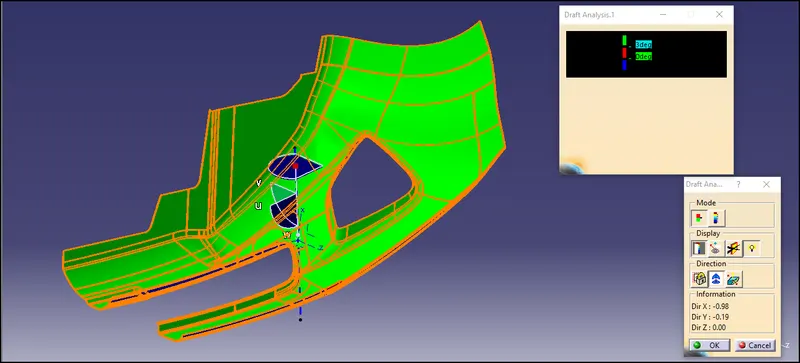
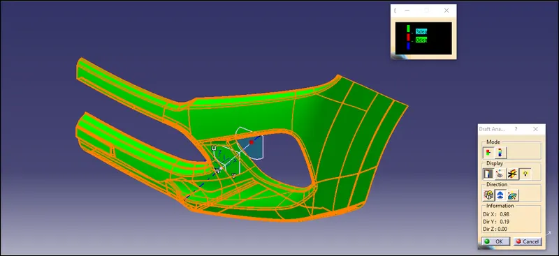
CONCLUSION:
The Bumper Plastic component through the given Class-A surface. To begin with, the tooling axis for the given Class-A Surface should be created meeting the requirements of the draft angle and at the end perform the Draft analysis on the model.
Taken the Thickness of the component to be 3 mm
CAT PART
FILE: KB
Bumper CATPart 9.44 MB