Week 8 - Challenge 3 - Switch Bezel Design
Switch Bezel Design
Aim: To Create the Switch Bezel Plastic component through the given Class-A surface.
Objectives:
• Creation of Tooling axis with appropriate draft angle.
• Creation of other surfaces (eg, B and C surfaces) for creating a solid component. • Perform Draft analysis on Class A surface and Solid model hence created.
Draft
The draft is the amount of taper for moulded or cast parts perpendicular to the parting. line. Draft angles are a design consideration that makes it much easier for a part to release cleanly from a mould. A draft angle is calculated as a degree measurement (or, less often, an inch or millimetre measurement) from the vertical axis of a mould, and it helps account for thermoplastic shrinkage, a practical reality of the injection moulding process for most materials.
Draft angles are generally a requirement of injection moulding design (though there are a select few soft materials, like nylon, that can get away with draft angles of zero). The draft should be a part of the design for manufacture, and all stakeholders and contributors should be aware of its need at the outset of the design process. This includes product designers, design engineers etc and this allows considerations for design requirements to be taken into account. Any draft is always better than no draft.
Importance of Draft:
By accounting for thermoplastic shrinkage during the cooling process, draft angles significantly reduce friction between the finished, cooled part and the side of the mould, Not only does this create a much easier release process, but it also offers several other benefits, depending on the design of the part which is as follows:
• Reduces the chance of damage to the part due to friction during the release.
• Reduces wear and tear and chances of damage to the mould.
• Ensures a uniform, smooth, unscratched finish when required. • Ensures the integrity and uniformity of other surface finishes and textures.
• Reduces overall cooling time by lessening or eliminating the need for unconventional ejection setups.
• Most, if not all, of these benefits, offer either direct or indirect overall production cost reductions.
Procedure for creation of Solid model:
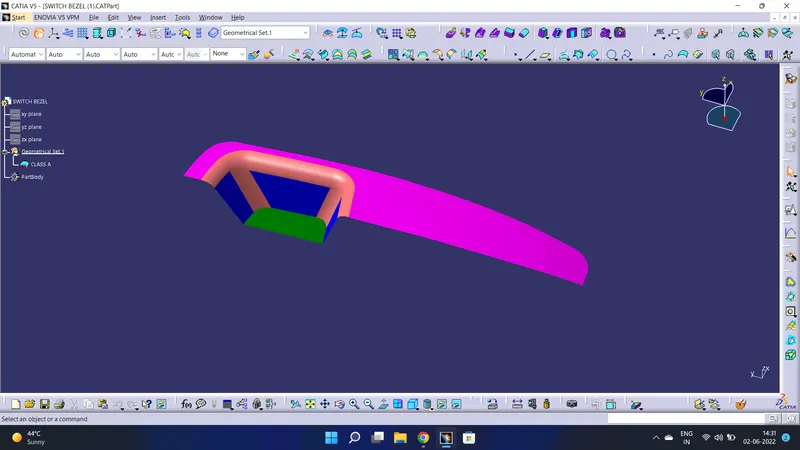
The image below shows the given class A surface for which a solid model is to be created.
Surface Inspection:
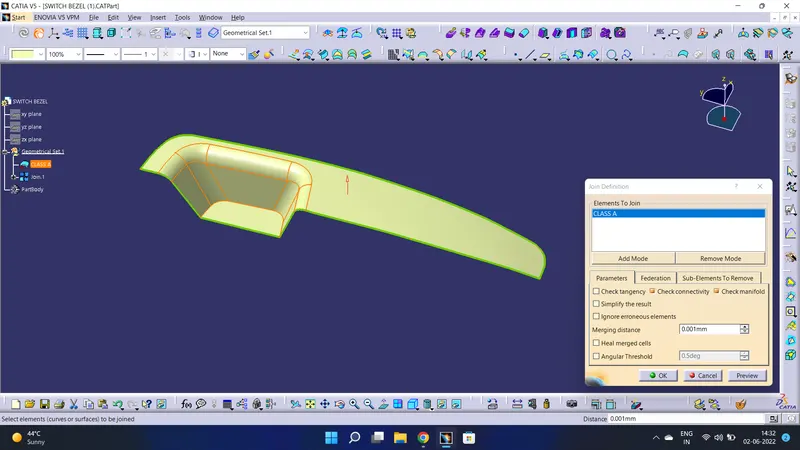
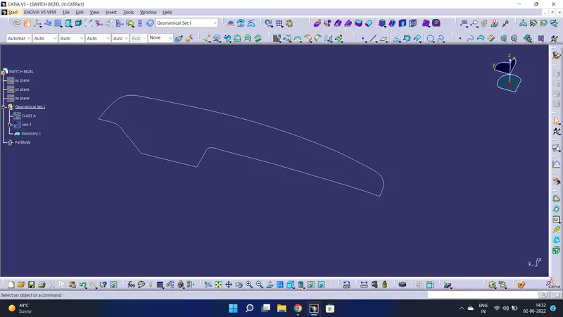
Firstly, the given surface is inspected for its quality/continuity such that no gaps are present in it thus clearing our way to go ahead with tooling axis creation
Tooling Axis creation:
It is defined as the direction in which the mould/core and cavity open. Selection of the direction of the tooling axis depends on the ease at which components can be easily ejected.
Hence the given surface is inspected for the tooling axis directions in standard X, Y & Z directions and accordingly best direction suited for the component is chosen. In this case, the flat bottom face is chosen and the axis perpendicular to the surface passing through its centre of gravity is created. We will name this axis as Dummy Tooling axis.
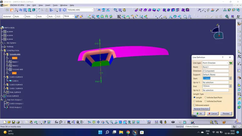
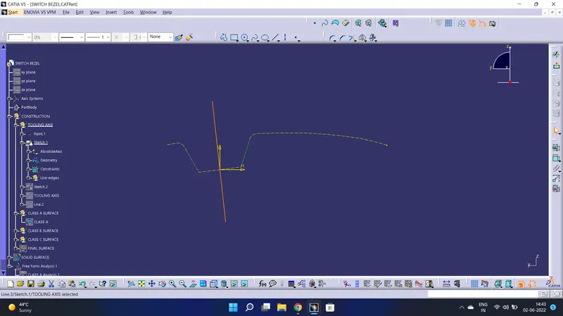
By analysing the component the most easily ejectable direction is somewhere close to the Z direction,(might be inclined to it) so we have made a sketch on the YZ plane of Axis System) to create a bisecting line considering the 2 faces which might be difficult to be tooled.
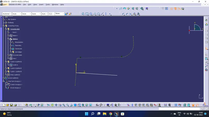
One more sketch is created on the ZX plane of Axis System for considering the lone side face for tooling direction. In the sketch, a line is drawn with a suitable angle to the lone
side face so that with the resultant tooling axis the side face is cleared.
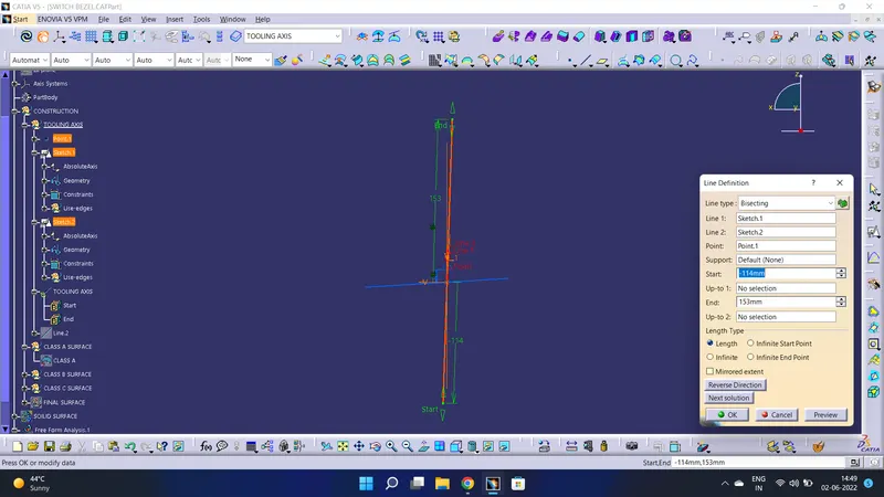
Then resultant tooling axis is created using the bisecting method.
Draft Analysis
Every part which is manufactured from a press tool or injection moulding process requires some positive draft on the faces which are parallel to the tooling direction. If we don't give a draft (Zero Draft) or give negative drafts on these faces it will stick to the mould surface and when the mould is in motion it will destroy the surface thus reducing its surface finish. Thus Draft Analysis command enables us to detect if the part we have drafted can be easily removed or not. It also gives insights into the critical zones, so that appropriate changes in the design can be made if needed.
To perform draft analysis on the given surface following steps are followed:
Firstly, in the View mode toolbar Customize view is selected and in that, the material option is selected as shown below.
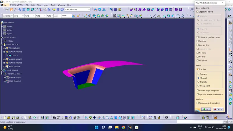
Compass is dragged onto the component and aligned with the tooling axis and the draft analysis is visible after clicking anywhere on the surface of the component.
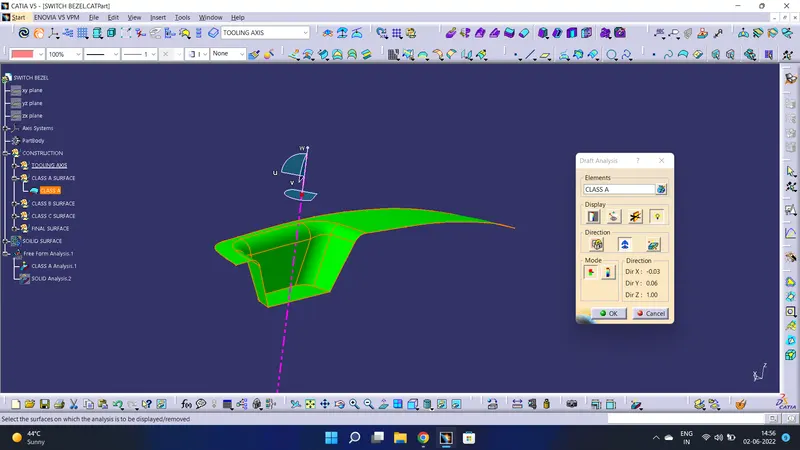
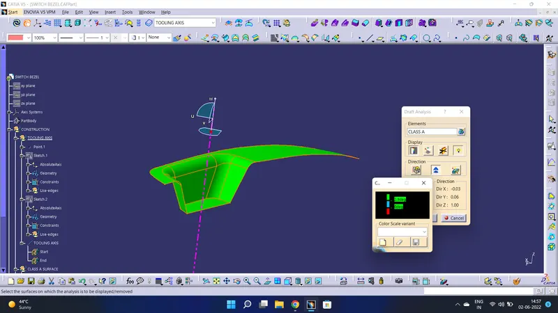
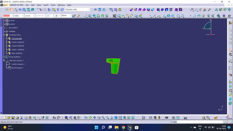
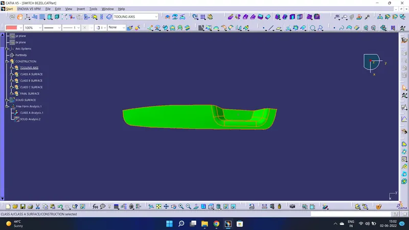
As we know minimum draft angle for the faces of the plastic component should be 3 degrees. So the value of 2.9 degrees (considering tolerance) is provided in the Draft analysis colour mode window. Inside the colour scale, the GREEN bar shows the draft angle of 2.9 or above 2.9 degrees. The blue bar shows below 2.9 degrees draft angle the other limit being 0 and the RED bar shows the negative draft angle. As shown below all the faces of the given Class-A surface are green hence it has cleared Draft analysis successfully.
3D Views of Class A surface with draft analysis
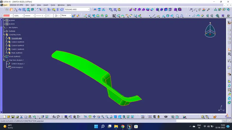
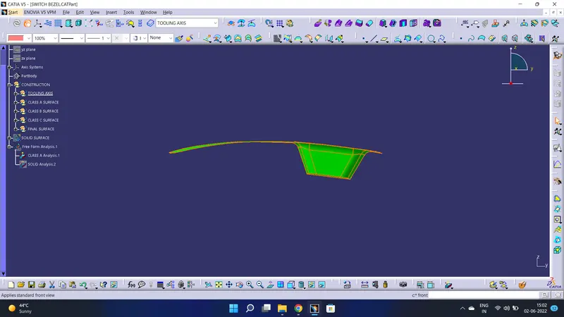
Draft Analysis of Solid Model
Same steps are followed to get the draft analysis of the solid part as in Class A Surface
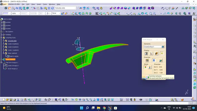
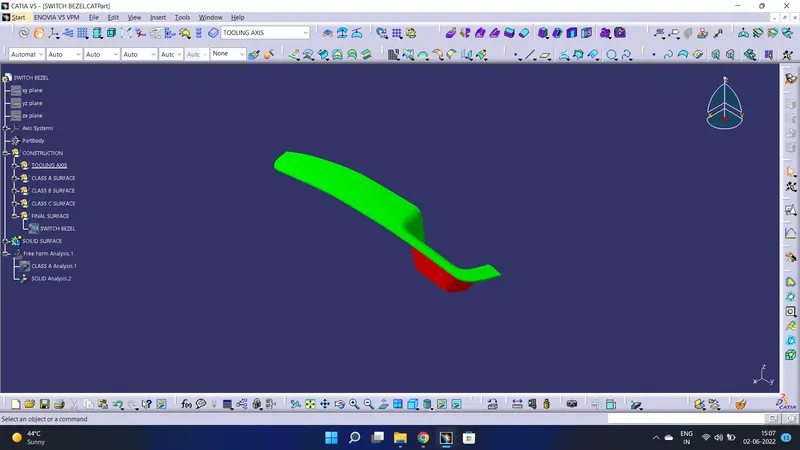
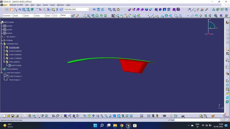
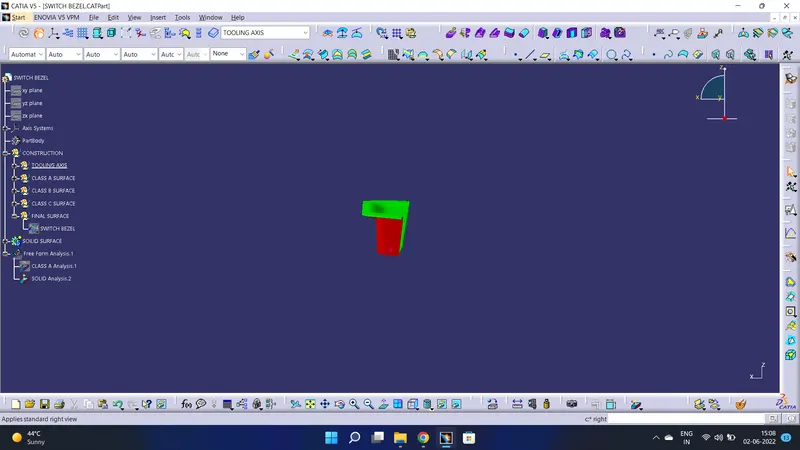
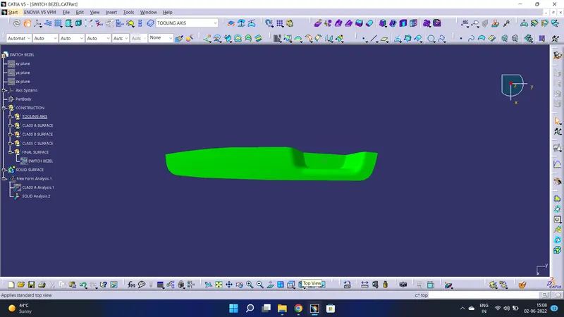
As we know minimum draft angle for the faces of the plastic component should be 3 degrees. So the value of 2.9 degrees (considering tolerance) is provided in the Draft analysis colour mode window Inside the colour scale, the GREEN bar shows the draft angle of 2.9 or above 2.9 degrees. The blue bar shows below 2.9 degrees draft angle the other limit being and the RED bar shows the negative draft angle. As shown in the image below all the top faces and side faces of the component are green, while the bottom faces are red. The line of demarcation between the green and red faces is the parting line which divides the core and cavity halves. The solid model has cleared the draft analysis successfully as shown in the image below.
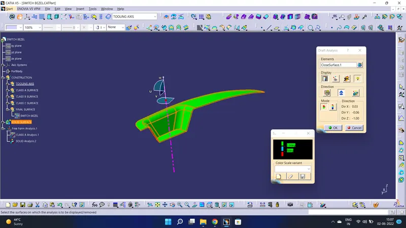
3D Views of the part model with draft analysis
FILE IS REVIWED BY POOJA