Week 8 - Challenge 3 - Switch Bezel Design
Automotive Plastic Design using CATIA V5
AIM: To Create the Switch Bezel Plastic component through the given Class-A surface. To begin with, the tooling axis for the given Class-A Surface should be created meeting the requirements of the draft angle and at the end perform the Draft analysis on the model. (Take the Thickness of the component to be 2.5 mm)
PROCEDURE:
- First import the surface or the CLASS A model to the CATIA V5.
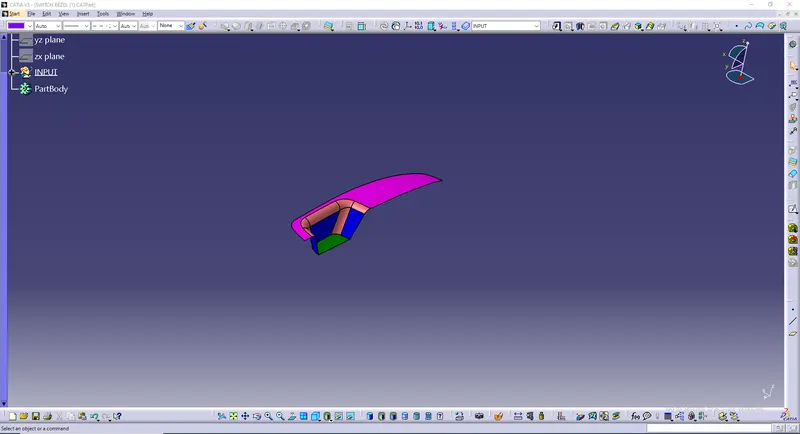
- As the switch bezel is a surface model we have to open it in the GENERATIVE SHAPE DESIGN which is observed in START << SHAPES.
- We have to check the Connectivity of the Class A surface which we have uploded.
- Ensure that there are no gaps between the surfaces on the class a surface.
- Create a point on the class A surface.
- Create a axis system on the class A surface by using the point.
- Now we have to create a tooling axis for the Class a surface. for that we have first create a new geometrical set named tooling axis.
- After creating the Geometrical set, we have to use create a sketch and intersect the model and draw two lines and bisect them to get the Tooling axis.
- Finally we get the tooling axis.
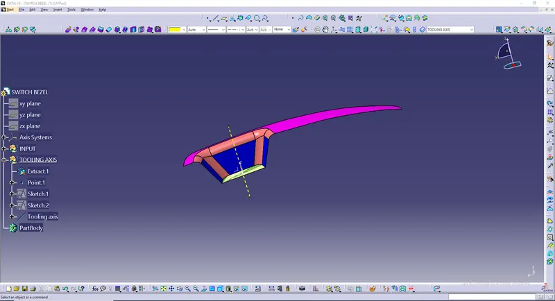
- Publish the Class A surface and the Tooling axis.
- Now we have to create the Class B surface.By using then class A surface we have to create the b surface by using commands like extract,un trim, and extrapolate
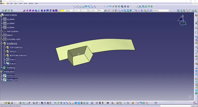
- Finally, apply the fillets to the B surface by measuring the fillets on the class A surface. and the class B surface is obtained.
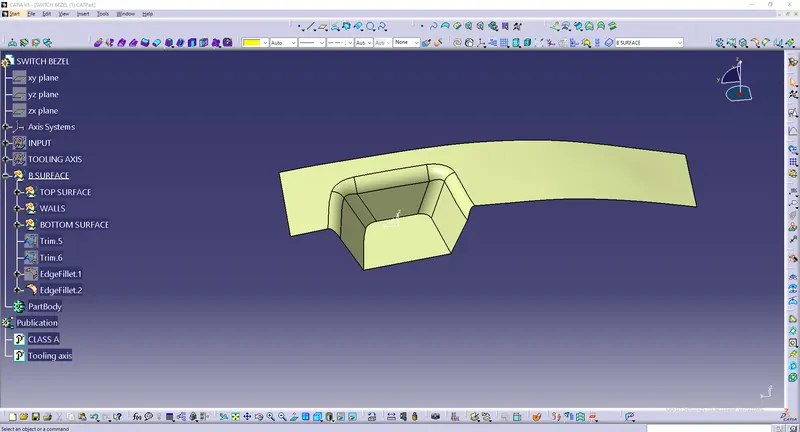
- Now we have to create the Class C surface
- Use Multi extract command and select the edges from class A surface.
- Use sweep command and select Draft angle and direction.
- Smooth the class C surface.
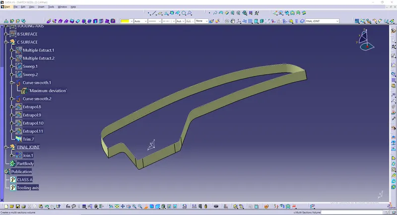
- Now we have all the 3 surfaces ."I had some problem in boundaries so I expoliated the class A surfaces and fixed the problem"
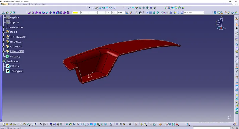
- create a closed surface od the model.
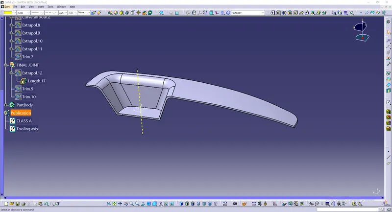
- Now we have to do the draft analysis on the model but before that set the viewing mood to material mood.
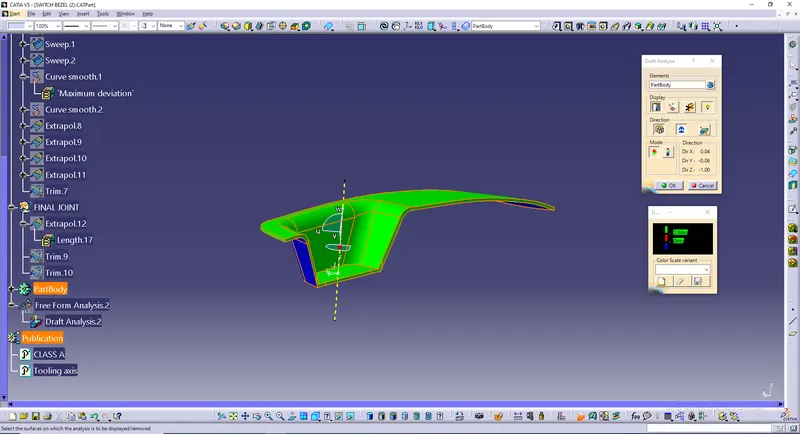
- Now, go to draft analysis,click in the compass option in direction and bring it to the tooling axis and lock the compass.
- Give the draft angle mim and max).
- Finally the draft analysis is performed on the model.
TREE:
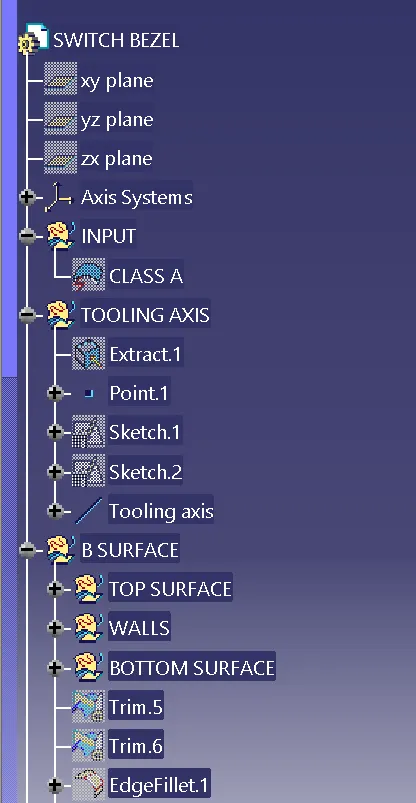
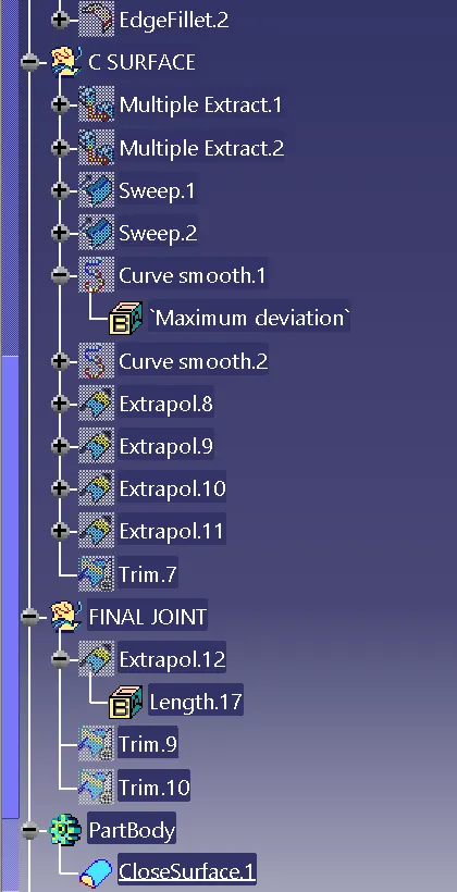
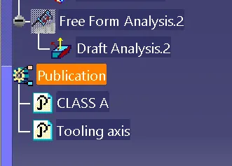
VIEWS:
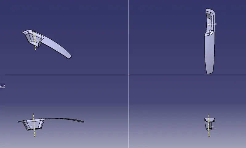
CONCLUSION:
Finally, We Created the Switch Bezel Plastic component through the given Class-A surface with, the tooling axis and we performed the Draft analysis on the model.