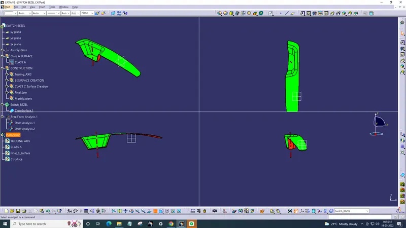
Week 8 - Challenge 3 - Switch Bezel Design
Report:
1. DRAFT ANALYSIS: It is a simple command which helps a manufacturer in checking that the plastic product which is formed in CORE & CAVITY can be removed from it easily or not. It can save a final product from wear and tear during ejection from the mold. The nominal range of Draft Analysis is between 0 to 3 degree.
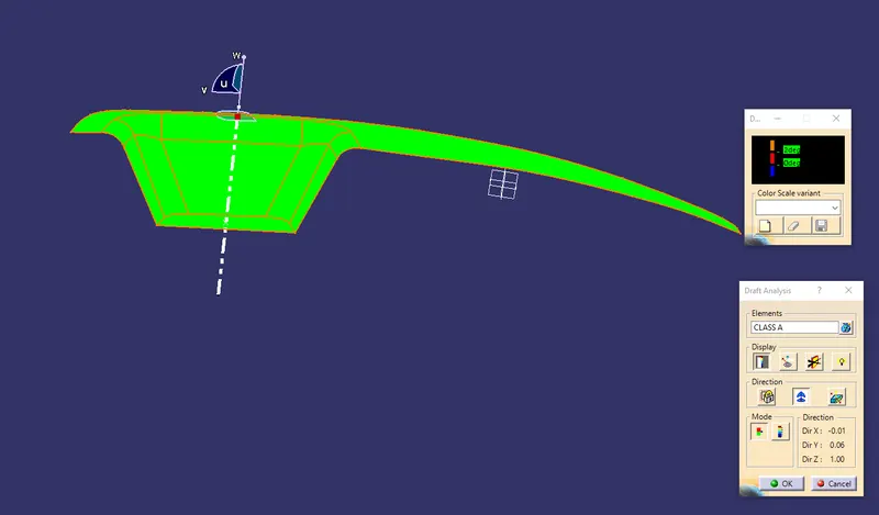
1.1 DRAFT ANALYSIS OF SWITCH BEZEL: There are two parts in this project in which we need to do draft analysis and that are CLASS A surface and final product of SWITCH BEZEL. The steps that I followed to obtain a proper draft analysis report for both of the class A surface and final product is mentioned as:
- Creation of Tooling Axis
- Setting up of Compass
- Selection of Target Surface
- Analysis of the drafted result
The final result which I obtained is green surface for CLASS A surface at an angle of 2 degree.
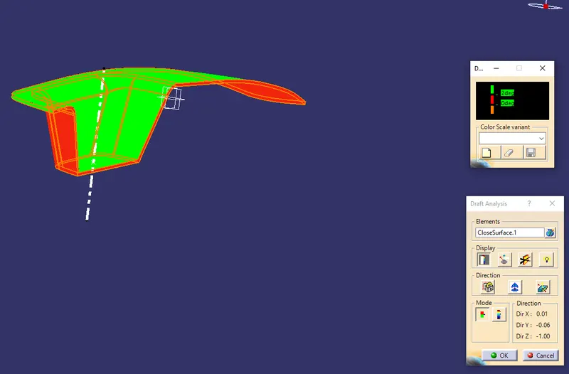
After that I moved to the final draft analysis phase in which I performed the draft analysis on the final closed solid product and I received green colour on the front/top surface and blue colour on the bottom or below surface as my result. After that I made some modifications and changed the lower bottom colour to red. The drafted results is calculated in between 0 to 2 degree for the closed product.
TOOLING AXIS: It is just like any other axis which provides a complete direction to the mould during opening and closing process after the completion of the manufacturing process. It is a particular path in which direction of the mould draft of a component is defined.

The above image is final tooling axis which I created on the CLASS A surface and for final product for draft analysis. I followed the tutor in the video and the method of creation of tooling axis is LINE BISECTING METHOD.
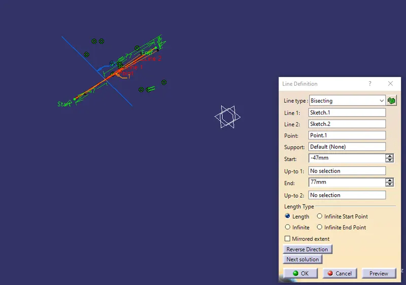
LINE BISECTION METHOD: In this method I created two tooling Axis on X plane and Y plane. Those two created tooling axis on X and Y plane are known as Dummy Tooling Axis.
1.2.1 DUMMY TOOLING AXIS ON X-PLANE

1.2.2 DUMMY TOOLING AXIS ON Y-PLANE

After that using these two sketches or dummy tooling axis I developed the bisecting line among these two by using a definite point for the same.
The Image of final tooling axis is as:
After that I used multi views option in order to get an allround views of the final switch bezel product.
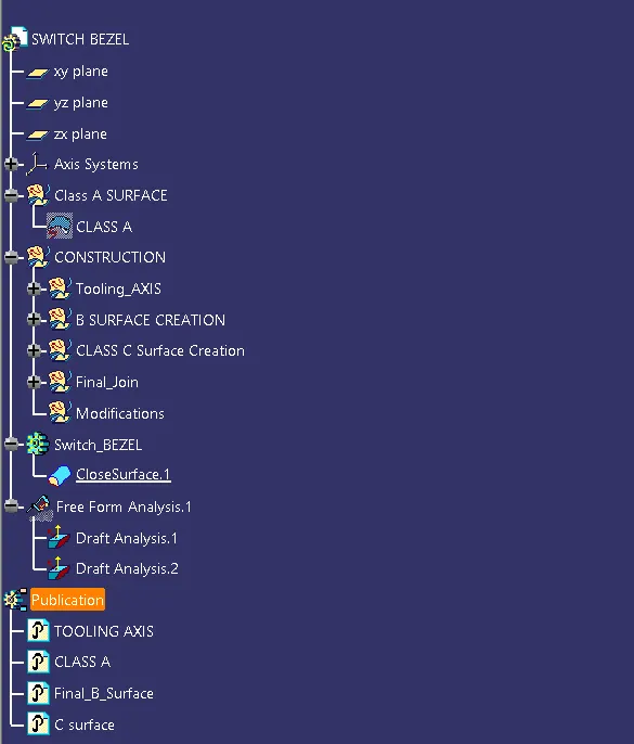
Here I am attaching the proper tree structure to accese my design developemnt through out the process.
And at last I am attaching the the multi face view of my switch bezel.