Week 8 - Challenge 3 - Switch Bezel Design
Aim: To create Switch Bezel Design by creating Class A, B, C surfaces.
Objective: To create a Design and perform a draft analysis on it.
Introduction:1. Class A surface: A surface that is given to the plastic modeler which is of aesthetic and outermost surface. The surface made by
the designer is known as a Class A surface.
2. Class B surface: A surface that is below the Class A surface, at a certain thickness, which contains engineering aspects on it is
known as Class B surface.
3. Class C surface: A surface that joins the Class A and Class B surface is known as a Class C surface.
Procedure:
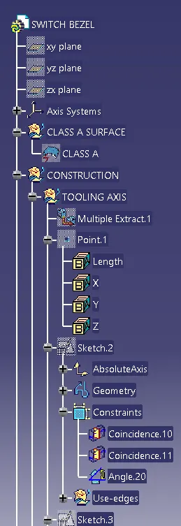
1. Creating a tooling axis
2. Performing draft analysis
3. Creating a Class B surface
4. Creating a Class C surface
5. Creating a solid model.
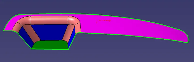
(X,Y,Z) DIRECTION OF TOOLING TO BE CREATED
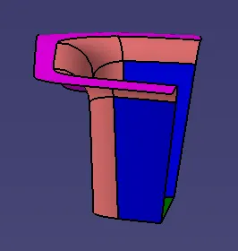
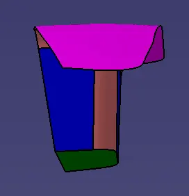
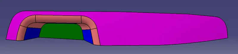
Creating a tooling axis:
Initially observe the class A surface and check whether the model contains any discontinuity and check joined properly or not. Check the model in all directions. Since there is only one possibility, we can go with the top plane and create an axis.
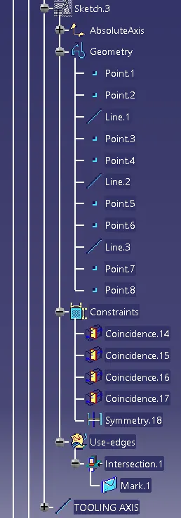
Creating an intersection at the required position. Creating a dummy tooling axis. Create two lines at the required intersection and bisect a new line with the previous two lines. Therefore we get a dummy tooling axis. Extracting the surfaces due to fillets are present and offsetting them for 3 mm.
The second method is checking the draft analysis with the help of a compass placing on the tooling direction. By checking the draft colours and placing on a particular axis and locking the compass. Now change the tooling line w.r.t to compass direction, then the final direction is set.
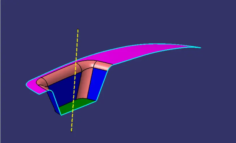
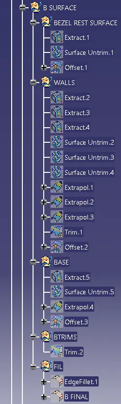
Extracting the surfaces and offsetting them.
Untrimmed and extrapolating surfaces. Trimming is done with intersecting surfaces
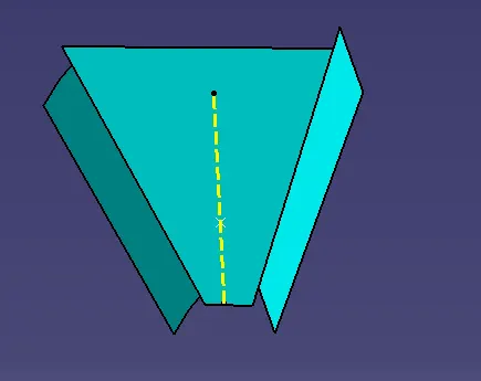
Extracting the surfaces and offsetting them.
Untrimmed and extrapolating surfaces. Trimming is done with intersecting surfaces.
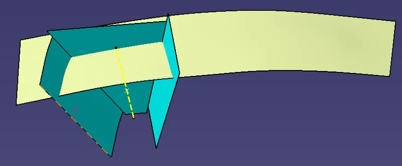
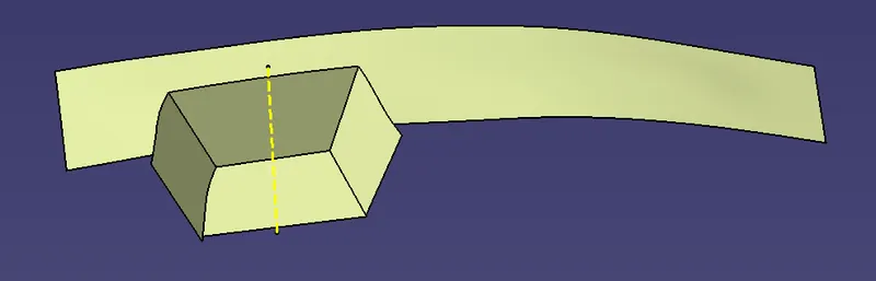
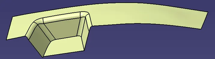
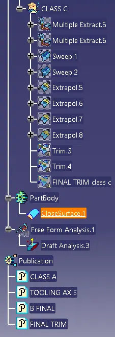
Creating the class C surface and extrapolating them. Trimming unwanted surfaces.
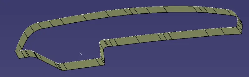
class C surface
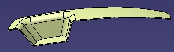
DRAFT ANALYSIS:
Performing draft analysis on solid model. CLASS C
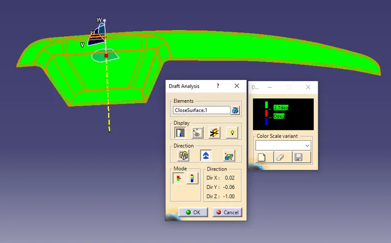
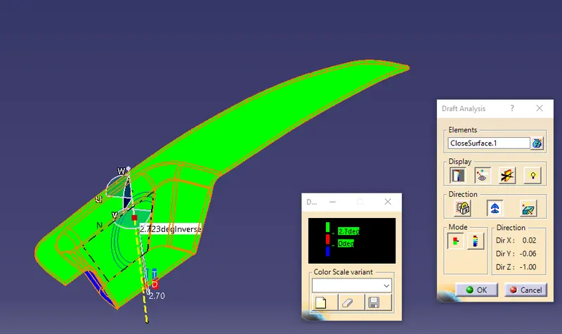
the angle is cleared with 2.7 drgree angle with positive
Performing draft analysis is done on Class-A surfaces
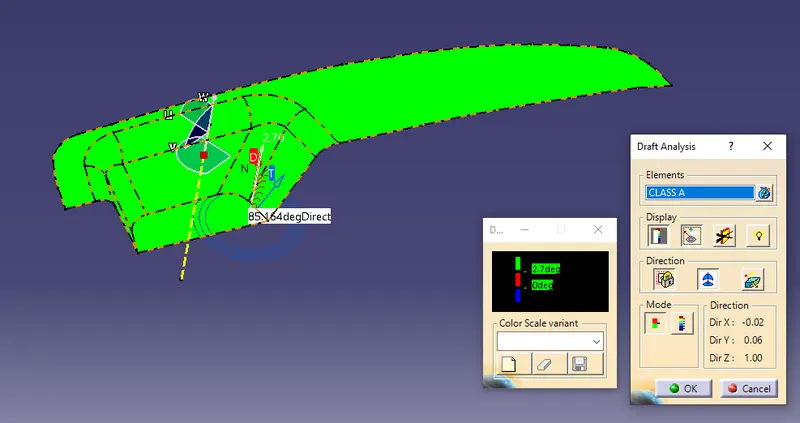
the draft analysis of a class A surface is clrared with 2.7 degrees
so the class C is created with the angle of 2.7 dregee as the class A is surface is not clearing above the 2.7 degree .
tree structure:
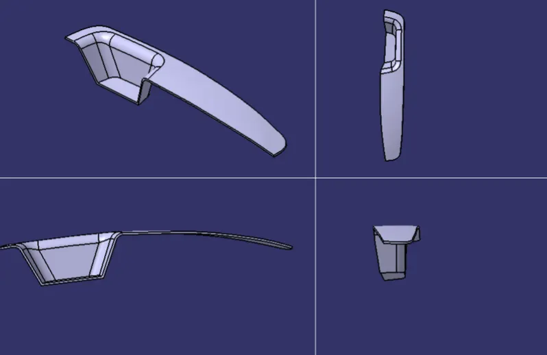
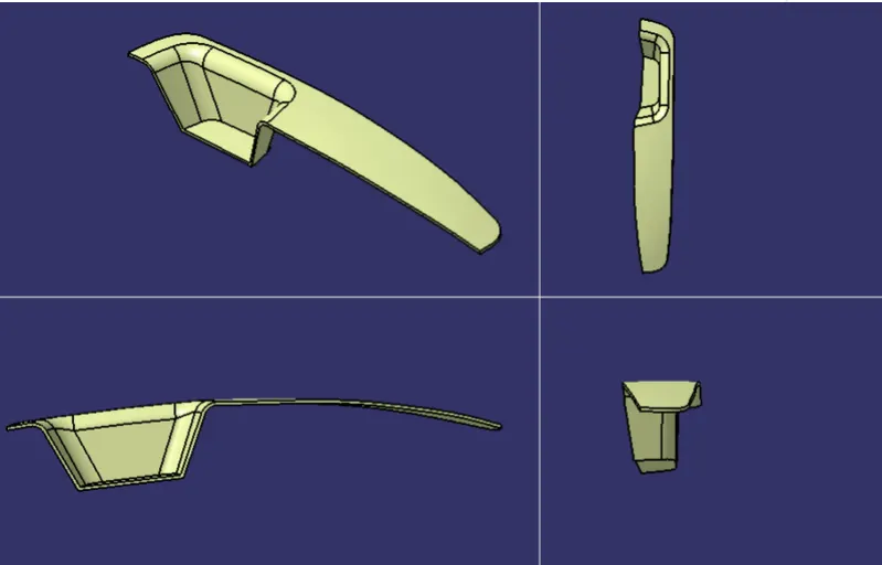
iso metric views:
front view:
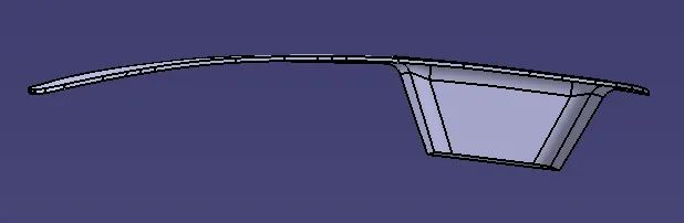
top view:
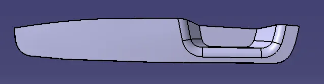
side view:
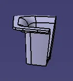
CONCLUSOION:
Creation of Class A, B, C surfaces and converting them into a solid model. Draft analysis is done on a Class A surface and a solid model is performed.