Week 8 - Challenge 3 - Switch Bezel Design
Aim:-
To create the Switch Bezel Plastic component through the given Class-A surface. To begin with, the tooling axis for the
given Class-A Surface should be created meeting the requirements of the draft angle and at the end perform the Draft
analysis on the model.
Take the Thickness of the component to be 2.5 mm
Objective:-
To ensure proper tree structure is followed.
Geometrical sets should have a proper name based on the sketches present inside of them.
All the sketches should be created under the geometrical set.
Using the close surface feature to make a solid body from the surface.
To publish the tooling axis,class A,B,and c surface.
Procedure:
TOOLING AXIS:
Step 1: Ensure there is no gapbetween the two neighbouring surfaces.
Operations>Boundary>Defintion>select component
Step 2 : Tooling Axis: Tooling axis is the direction in which mold or core and cavity is opened.
We have to check all possible tooling directions in all the three axes. When we are
deciding the tooling axis we have to make sure that all the faces should be visible to that
tooling axis, no face should be hidden.
For this component Zaxis will be the best tooling axis as we can see all the faces of the
component and can be cleared in x and y axis direction.
STEP 3: To make tolling axis we have to follow following steps
Multiple extract the base surface
Place a point in between of the surface> Point definition select surface > Distance
0 mm
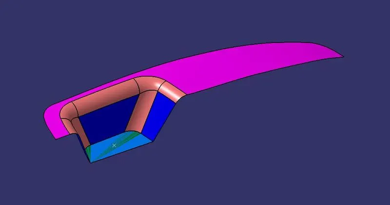
Step 4: Place the axis system on that point.
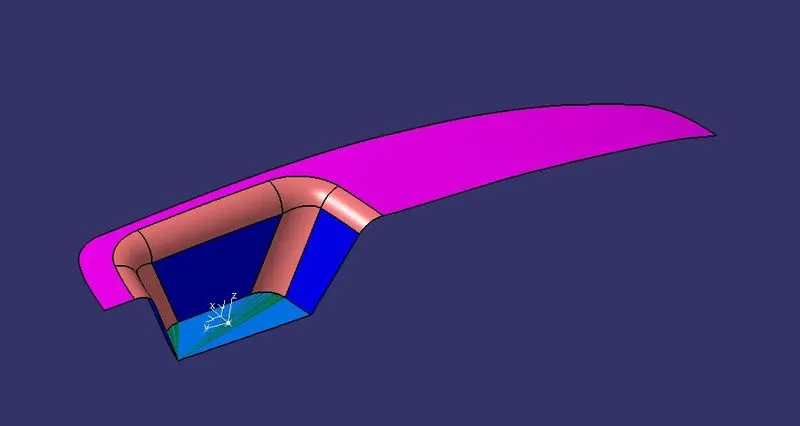
Step 5: Sketch for tooling axis along Y direction.
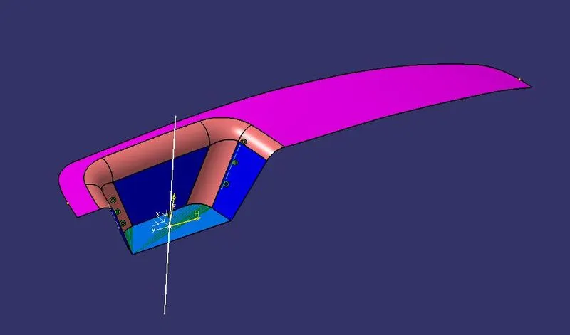
Step 6: Sketch for tooling axis X direction.
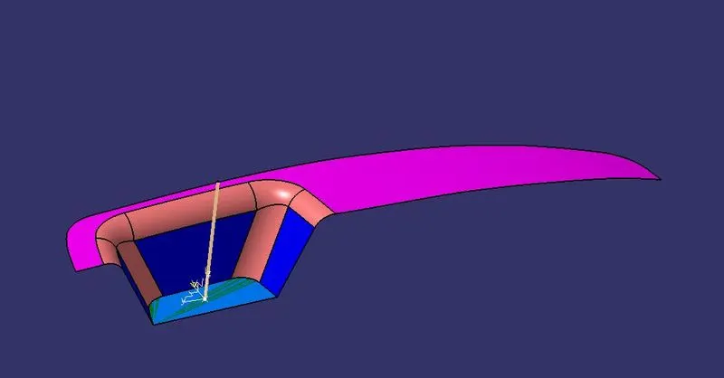
Step 7: Extract tooling axis along Y and X direction
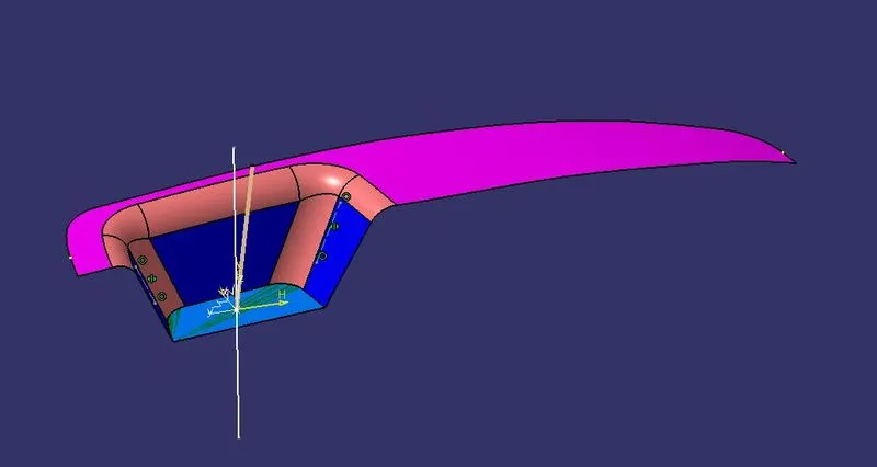
Step 8: Bisect tooling axis X and Y to get component tooling axis.
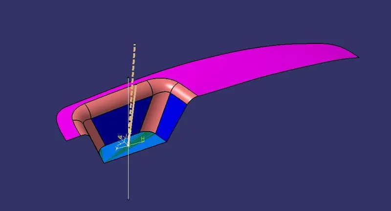
Step 9: Rename,change color and give thickness to the tooling axis so that it can be easily identified.
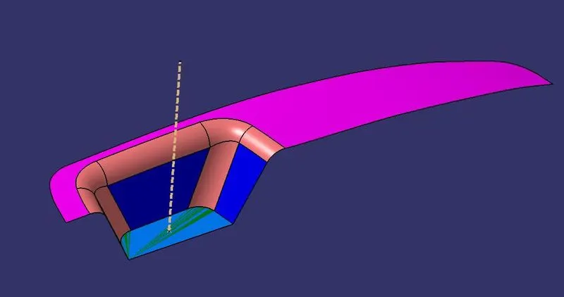
Step 10: Publish tooling Axis and Switch bezel Component.
Select this two in model tree>Toolbar>Tool>Publication>ok
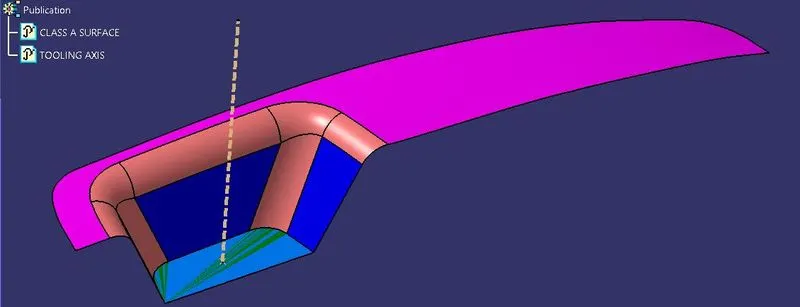
PROCEDURE FOR DESIGN:
Step 1: Extracting surafces from bezel arm surface.
Extarct the surface
Untrim that extracted surface
Offset it inside to 2.5mm.
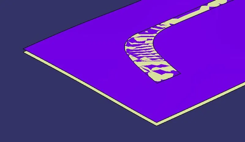
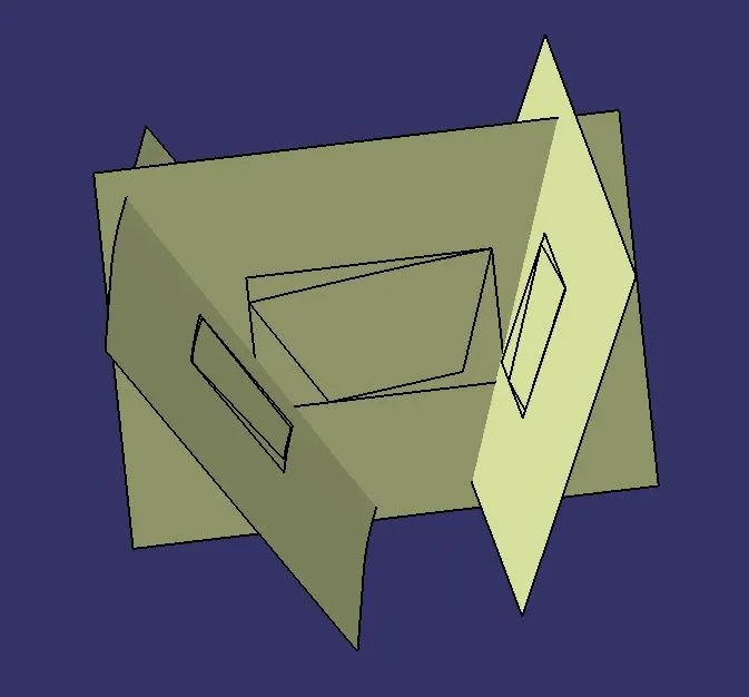
Step 2: Extracting surfaces from Bezel Wall
Extract all three surface
Untrim that extracted three surface
Extrapolate all three surfaces till they intersect with each other.
Offset it inside to 2.5mm
Trim the surface as required in the component.
Step 3: Extracting Surfaces from Bezel base surface.
Extract thge surface
Untrim that extracted surface
Extrapolate the surfaces till they intersect with the wall offset surface.
Offset it inside to 2.5mm
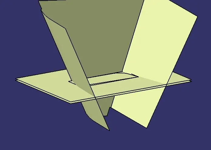
Step 4: Extracting fillets from Bezel surface
Extracting fillet surface and untrim them will help us to know the exact value of the fillet radius.
Extract few fillets.
Untrim that extracted surface.
We get to know that the fillets are 14mm and 15mm.
Step 5: Change the color of the offseted surfaces
Step 6: Trim the offsetted surfaces as required in the component.
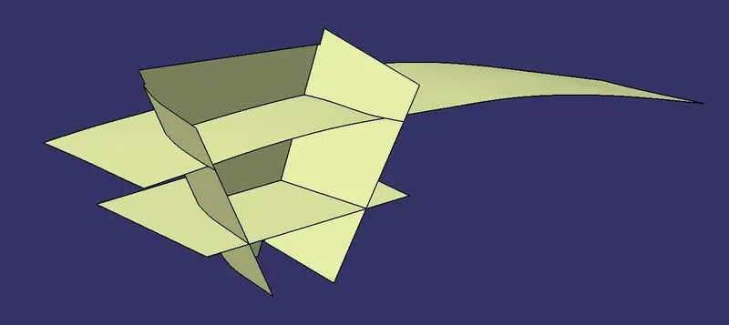
We can see the surfaces of the component after trim as below -
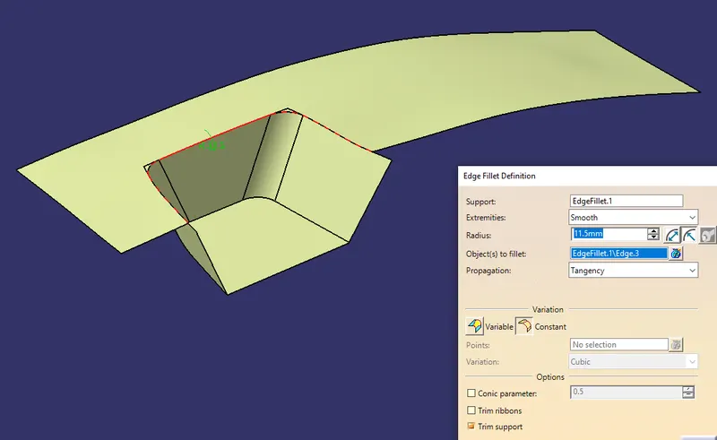
Step 7: Give edge fillet radius of 15mm actual radius in addition with 2.5mm of the thickness of the component.
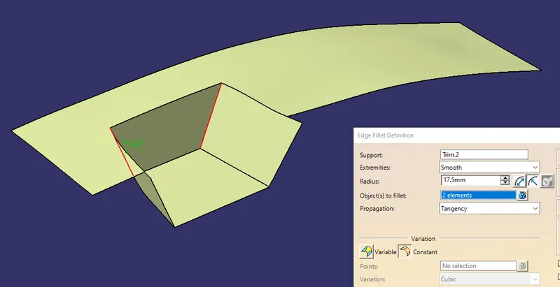
Step 8: Give edge fillet radius of 14mm actual radius in subtraction with 2.5mm of the thickness of the component.
We can see the surfaces of the component after fillet as below-
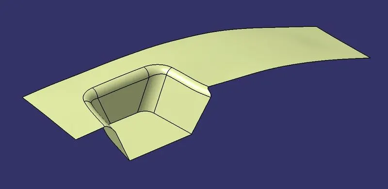
NOTE: measure the surface thickness of B surface and A surface with the help of vernier calliper it should be 2.5mm
throughout between the surfaces
Step 9: Extract the tangetial boundary from one side of the A surface.
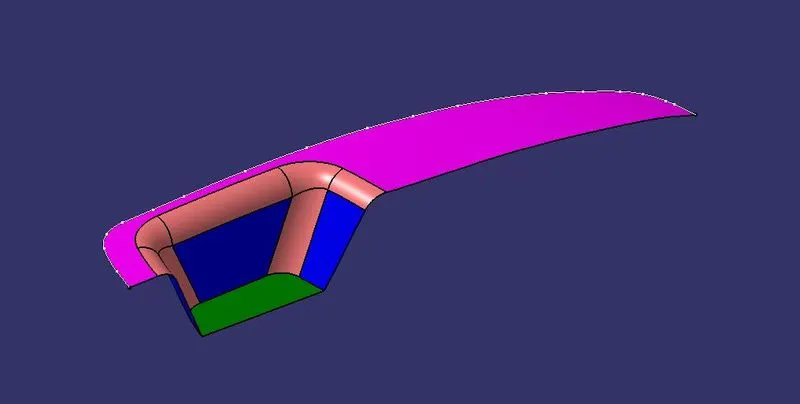
Step 10: Extract the tangential boundary from the other remaining side of the A surface.
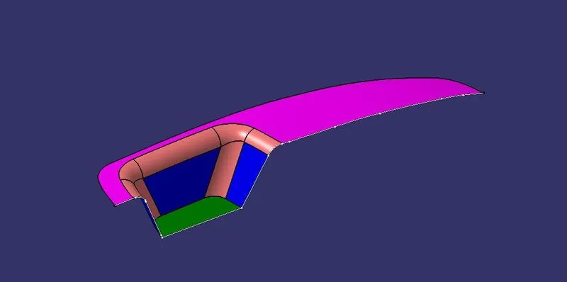
Step 11: Smooth both the lines to avoid seeing the patches in the surfaces.
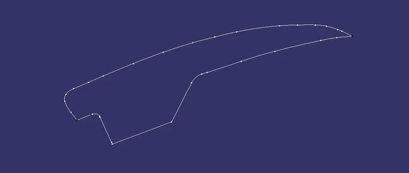
Step 12: Sweep one boundary with sweep with direction panel
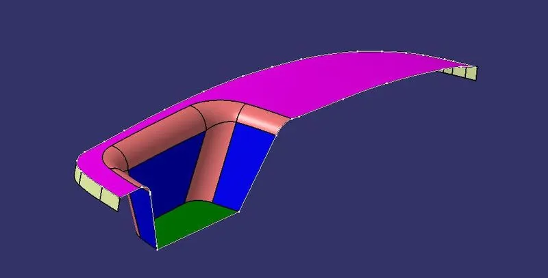
Step 13: Sweep another boundary with sweep with direction panel.
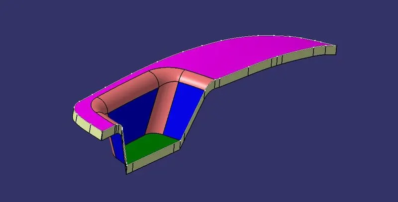
Step 14: We can see the gap between the two sweep surfaces.We can fix this by following steps.
Extrapolate all the four free edges to few millimeters.
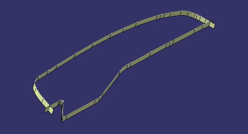
Step 15: Trim the extrapolated surfaces as required in the component.
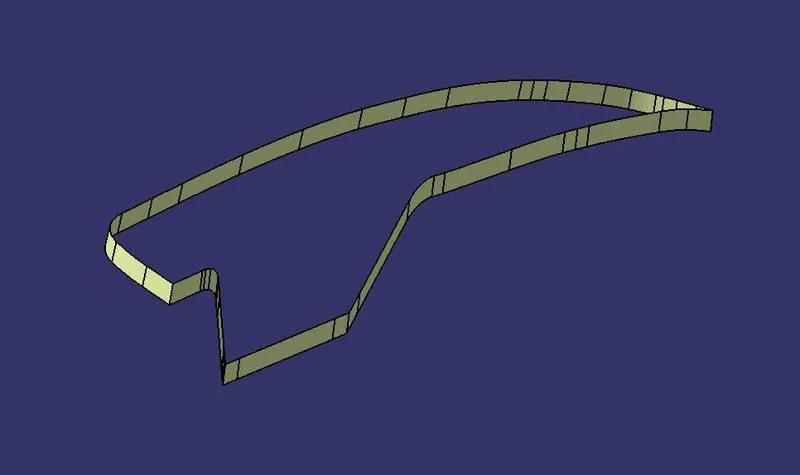
Step 16: Join the final trim (sweeped surfaces) and A surface.
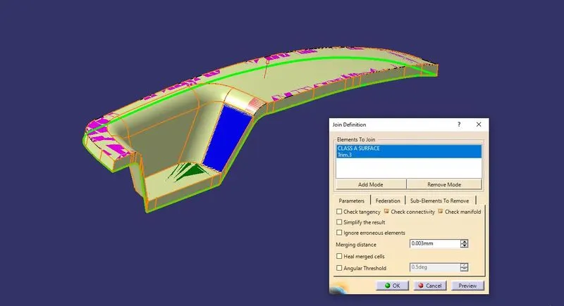
Step 17: Trim C surface and B surface to get thicken part.
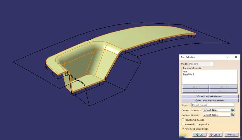
We can see the thicken C surface after trimming as below
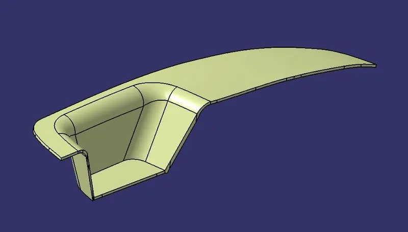
Step 18: Switch to part design workbench.Define part body to make Switch bezel C surface into a solid component by surface panel.
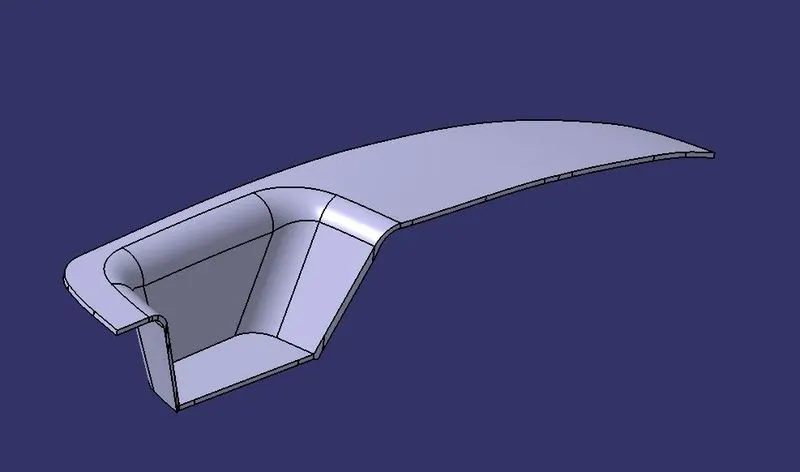
Procedure to check Draft Analysis:
Check draft analysis on final part body.
Step 1: Changing view mode to material.
View mode>view mode customization>tick material>ok
Step 2: Calling Draft Analysis.
Toolbar-Insert Analysis Feature Draft Analysis
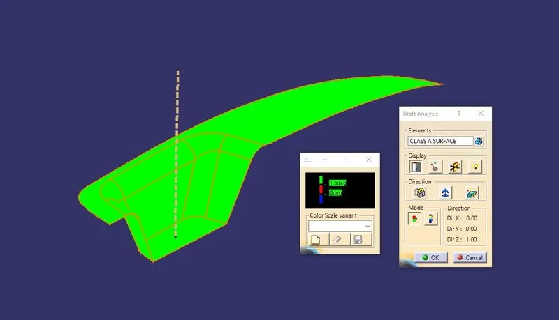
Step 3:
- Drag the compass from the draft analysis box on the tooling axis and place it property.
- Click on locks so compass will get locked to tooling axis.
- Click anywhere on the component. Click OK.
- Analysis the colour of the failing and passing surfaces.
If a component is showing in Green colour that means our component is ready for manufacture.
NOTE: If we find zero degree or negative degree filing colour, we can fix it by changing
draft angle, sweep direction, modifying properly tooling axis etc.
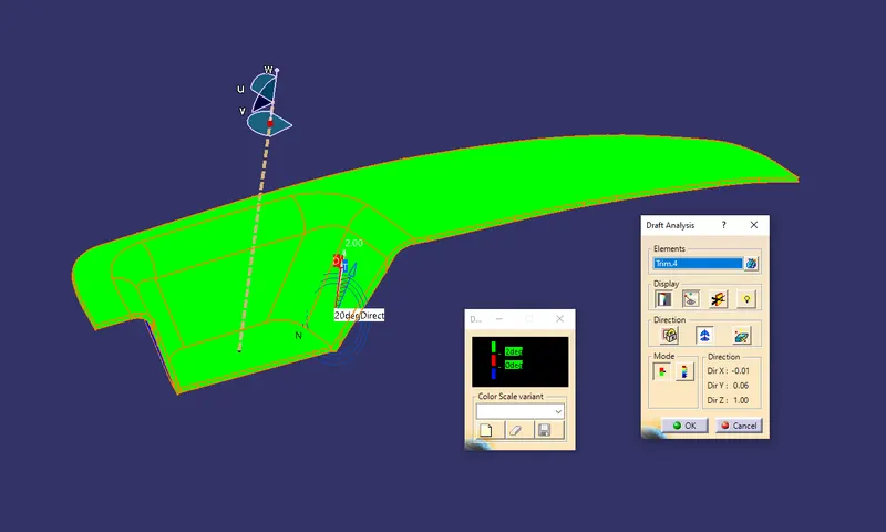
Draft Analysis of Class A Surface:
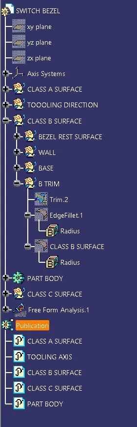
Tree Structure: