Week 8 - Challenge 3 - Switch Bezel Design
PLASTIC DESIGN SWITCH BEZEL
AIM:- Create the switch bezel plastic component through the given Class-A surface and create tooling axis, perform draft analysis and also create class B surface and Class-C surface.
INTRODUCTION:- The draft allows the part to easily eject from the mold. The draft angle is to reduce friction between the core, cavity, and part and it also avoids damages. The minimum draft angle is 0.5 degrees and the most common draft angle used in the plastic design is 3 degrees.
In Catia the draft analysis is performed based on color ranges identifying zones on the analyzed element where the deviation from the draft direction at any point, corresponds to specified values.
Tooling direction is the main element that is to be considered while designing a plastic component. In the molding machine, the arrangement is given to open the mould along the direction. It is the direction in which the core and cavity open.
Class-A surface
In automotive design, a class A surface is any of a set of freeform surfaces of high efficiency and quality. Although strictly, it is nothing more than saying the surfaces have curvature and tangency alignment – to ideal aesthetical reflection quality, many people interpret class A surfaces to have G2 (or even G3) curvature continuity to one another (see free form surface modeling). Class A surfacing is done using computer-aided industrial design applications. Class A surface modelers are also called "digital sculptors" in the industry. Industrial designers develop their design styling through the A-Surface, the physical surface the end-user can feel, touch, see, etc.
Class-B surface
These are the surfaces we see sometimes, are secondary surfaces, but are less important. These surfaces also must be smooth and free from any errors but are held below Class-A quality as these surfaces will not affect the aesthetic appearance of the part. It usually has ribs, boss, snap, etc.
Class-C surface
These are the backside of the surface of the component which comes in contact with other assembling parts/components. These surfaces can have tooling marks, abnormalities, or flashes. These surfaces are equally important for fit and assembly purposes. These are not majorly important from an aesthetic perspective.
Procedure:-
First, the continuity should be checked in the given Class-A surface. By using the boundary option.
Tooling axis:
- Extract the base of the switch bezel using the multiple extract option. Create an option on it using on surface option.
- Insert axis system in the point, create a sketch on it using the YZ plane.
- Make an intersection on it, draw two inclined lines and the point create a line which is the tooling axis Y.
- By using the same method create a sketch on the XZ plane that makes an intersection on it. Draw a line on the intersection and draw another line which is 5 to 6 degrees from the first line. Which is the tooling axis X.
- Create a bisecting line using the X & Y tooling axis we get the tooling axis and publish it.
Class B Surface Creation
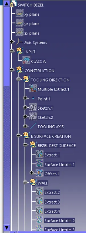
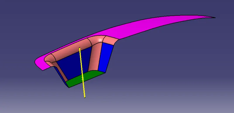
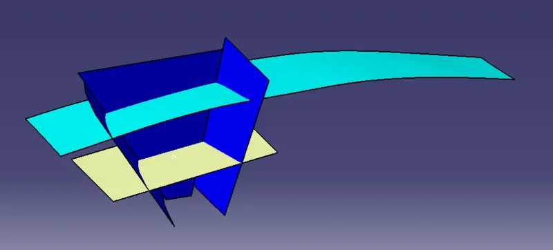
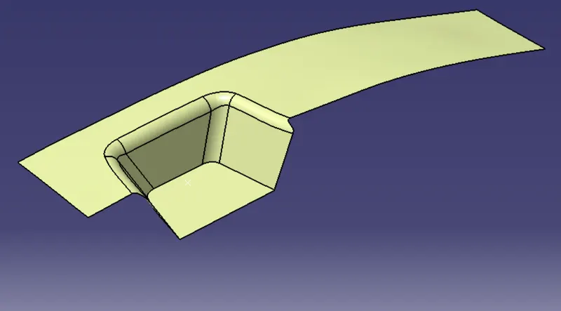
- Create the class B surface one by one first the Bezel rest surface (Pink color) extract the surface, untrim the surface repeats this operation for the walls and base surface of the switch bezel.
- For the base and wall, offset the surface for 2.5 mm which is the thickness of the component.
- Trim all the surfaces to form the class B surface.
- Now perform the fillet operation.
Class C Surface creation
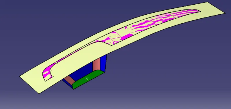
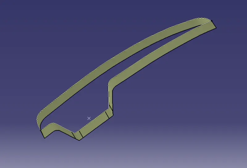
- The edges of the Class A surface are extracted using the multiple extracts and then converted into smooth curvature to avoid the patches.
- The sweep (with draft direction) option is used selecting the smooth curves as the guide curve and tooling axis as the direction and draft angle as 3deg.
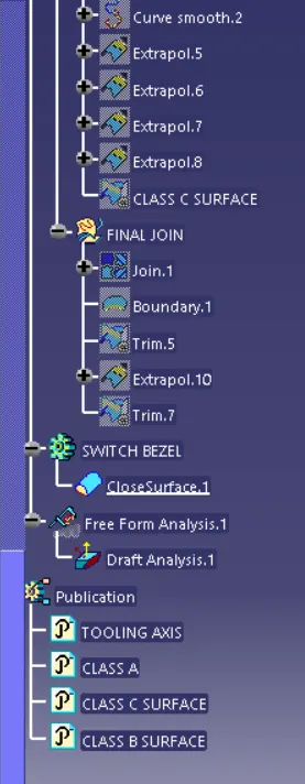
- Trim the sweep that was created and join it with the Class A surface.
- Then trim the Class C with Class B surface.
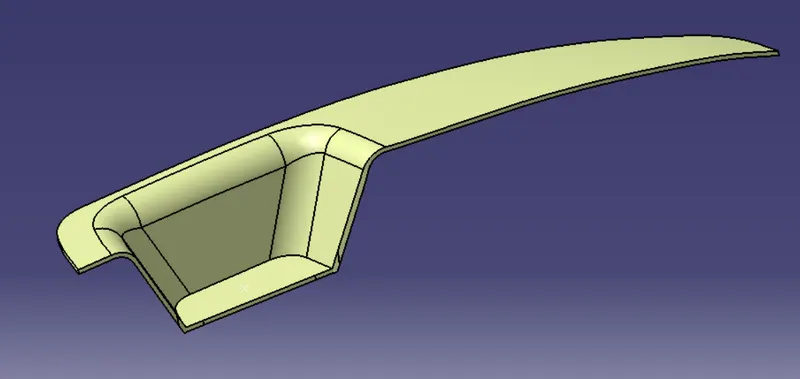
Solid-body Creation
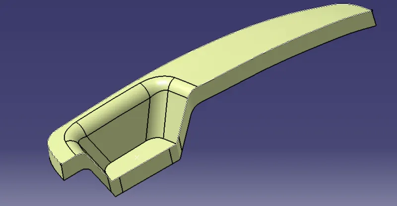
- Before creating a solid body the surface part has to be checked whether are there any gaps in between it.
- If there are any gaps they can be joined using the extrapolation and trim option.
- Define the part body and use a close surface option to make it a solid body.
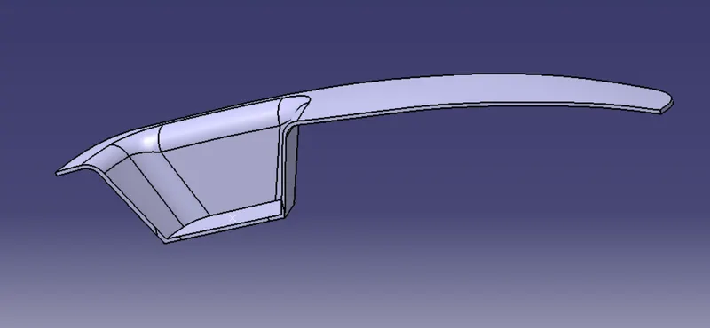
Draft analysis
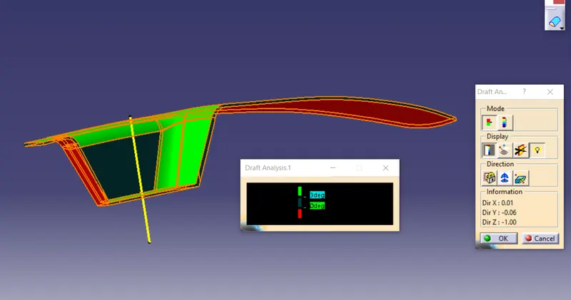
- For plastic parts, the nominal draft angle is 3 deg. But even 7deg is allowed for the subassemblies like ribs and slots.
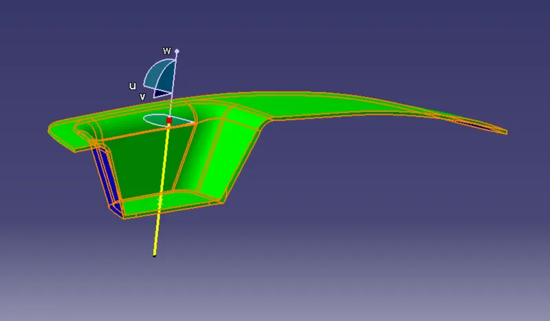
- First, the compass is moved to the part (the compass should be placed on the tooling axis) which is used to define the new current draft direction, then lock the draft direction using the lock icon.
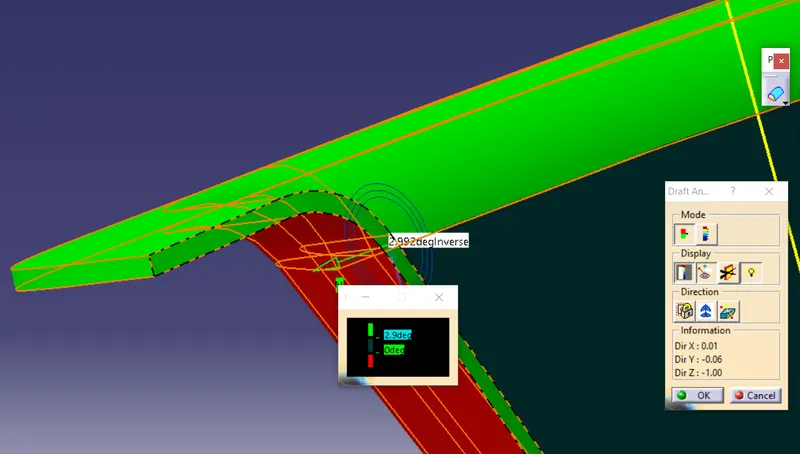
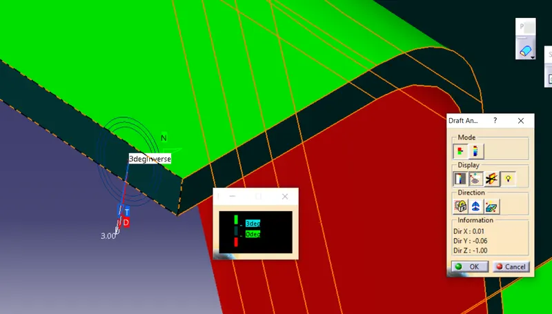
- The color chart indicates the various condition of the draft angle. The green color indicates that the part passes and can be used for further operations.
- By using the analysis under the running point icon we can check the draft angle at the various surfaces of the component.
- There are two modes in the draft analysis quick mode and the fully detailed model.
- If the surface satisfies the 3deg then it shows in green in color if not appears in red color.
CONCLUSION:-
The Class B, Class C, and the solid body of the switch bezel are created from the given Class-A surface and the draft analysis is performed.