Week 8 - Challenge 3 - Switch Bezel Design
AIM - To Create the Switch Bezel Plastic component through the given Class-A surface. And to perform the draft analysis on the model.
PROCEDURE - Here Class A Surface which is given to me is shown below:
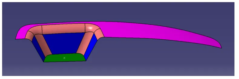
Now from the above-shown fig. I have to create the solid component creating the CLASS B and CLASS C surface. so first I will create the tooling axis.
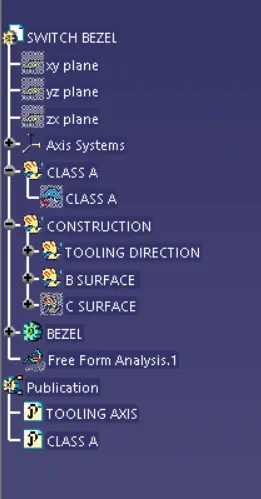
The tree structure of the model is shown below:
Tooling axis - The tooling axis is defined as the direction in which the mold opens or core and cavity opens and closes. The selection of the correct tooling axis is
important to ensure the component is taken out perfectly and also the cost of the component should be less.
I will start by insering a geometrical set and naming it as a tooling direction. For creating the tooling axis I will analyze the model and see from which direction I can
see the whole model. So on analyzing the model I found out that the z-axis will be perfect for creating the tooling axis. Because along Z direction only the whole
component is visible.
For creating the tooling axis first I will extract the base from the class A surface. And will create a point on the center of that base. Then I will insert an axis system
on that point.
After creating the axis system I will create two sketches on the YZ and XZ plane of the axis system that is because if I'm choosing the tooling direction as z the
component should be clear in x and y-direction.
The first sketch is shown below:
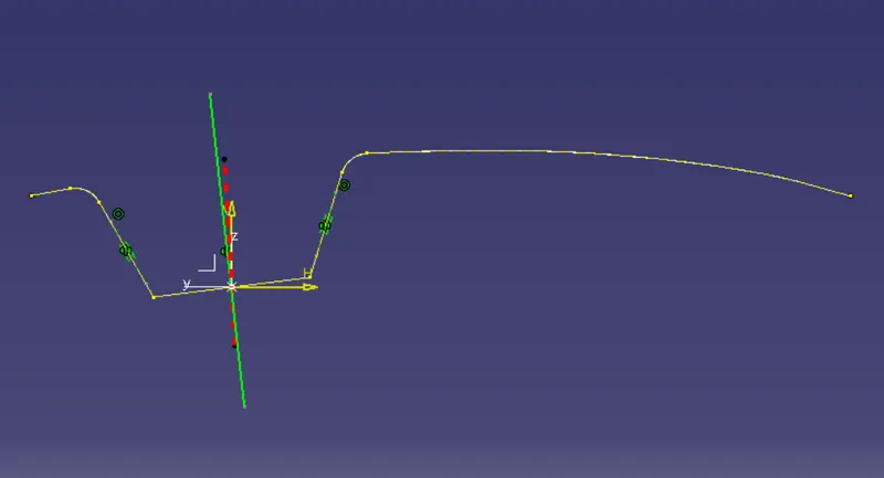
In the above fig., u can see that one bisecting line is created using the two lines which is the intersect of class a surface in yz plane. So that line will give the tooling
clear for y-direction.
The second sketch is shown below.
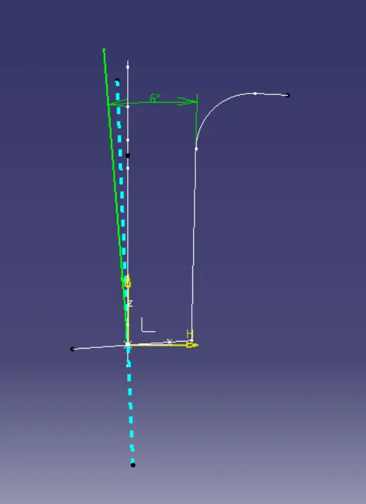
n the above fig one line is created at 6 degrees from the intersect of class A surface on the XZ plane of the axis system. so that line will give me the tooling clear in
the x-direction.
now I will create one line bisecting the two lines which are the tooling clear for y and tooling clear for x. That bisecting line will be my tooling axis.
The tooling axis parameters are shown below:
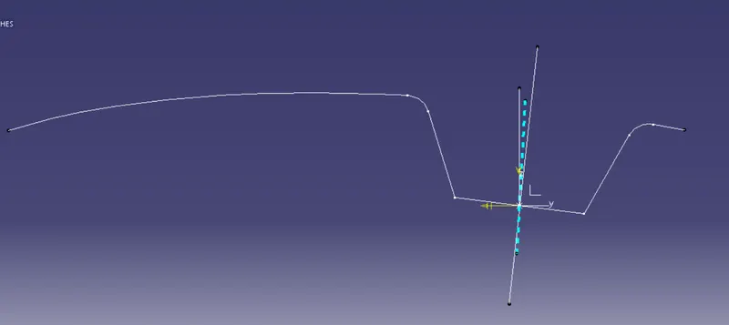
So here I have created the tooling axis and it is shown below:
After creating the tooling axis I will create the CLASS B surface using the class A surface.
CLASS B SURFACE - It is a surface that gives thickness from class A surface. All the supporting features of the component will be formed on the B surface only. so
we can say that Class B is an engineering surface and Class A is an aesthetic surface.
For creating the B surface first I will insert a geometrical set and name it as B surface creation. I will start by extracting the surfaces so first I will extract the bezel
rest surface. The extract is shown below
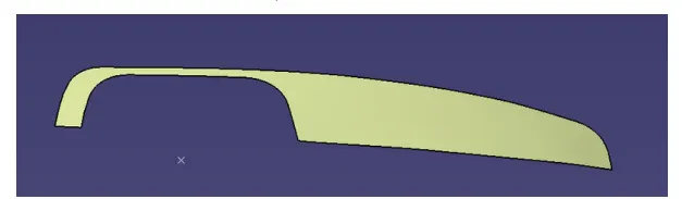
Then I will untrim this extract. The untrim is shown below
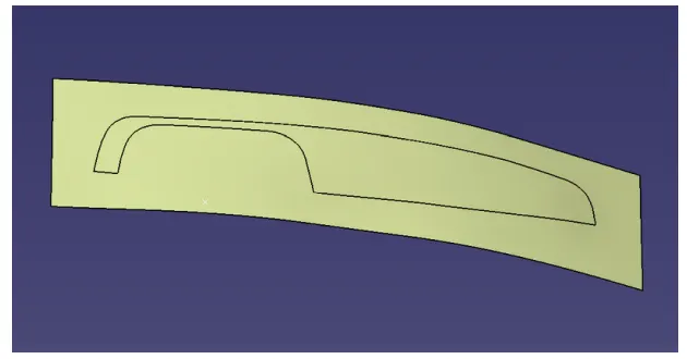
Then I will offset the above untrim surface to 2.5 mm because that will be the thickness of the component.
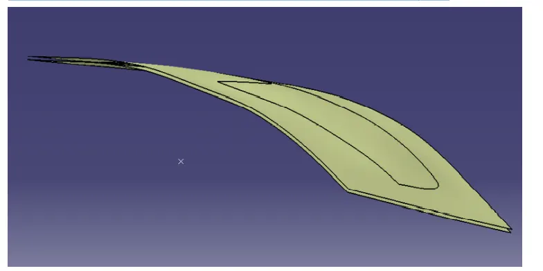
After doing the bezel rest surface I will create the walls following the same procedures as I did it above. The extract of the walls is shown below
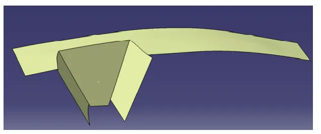
Then I will trim the base with the above trim. the final is shown below
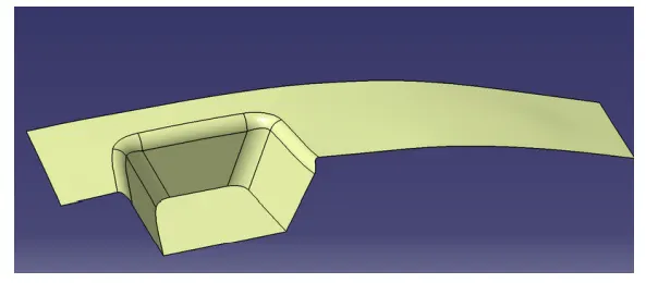
After the creation of the class B surface, I will create the class C surface
CLASS C SURFACE - Class C surface is defined as the surface which connects the CLASS A and CLASS B SURFACE along the tooling direction. The tooling
direction here will be my tooling axis.
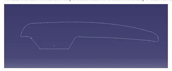
For class C surface I will use the multiple extract feature to extract the boundary of class A surface. the multiple extracts is shown below:
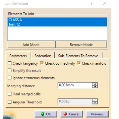
Then I will join the class A and class C surface. The join parameter is shown below:
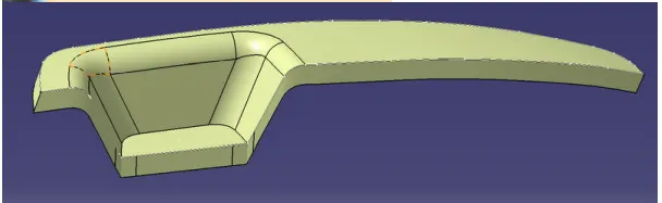
Then at last I will trim the Class B surface with the join of Class A and Class C surface. The trim is shown below:
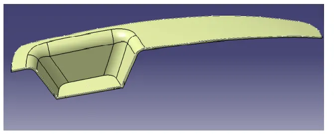
Then I will to part the body and i will create a solid body of the above-closed surface. The solid body is shown below:
Then I will perform the draft analysis of the switch bezel model that I created.
Draft analysis - Draft analysis is a technique to analyze whether the component created is manufacturable or not based on the draft conditions applied. So here I
will provide the direction in which the component should be ejected to get the easy removal. My dirction will be the tooling axis that I have created.
The minimum draft value for the Automotive plastic component is 3 degrees and those for the texture faces 7 degrees od draft is suitable. The draft is provided to
the component for easy removal from the mold in case of the plastic components.
So here I will change the customize view parameters and will select the material mode
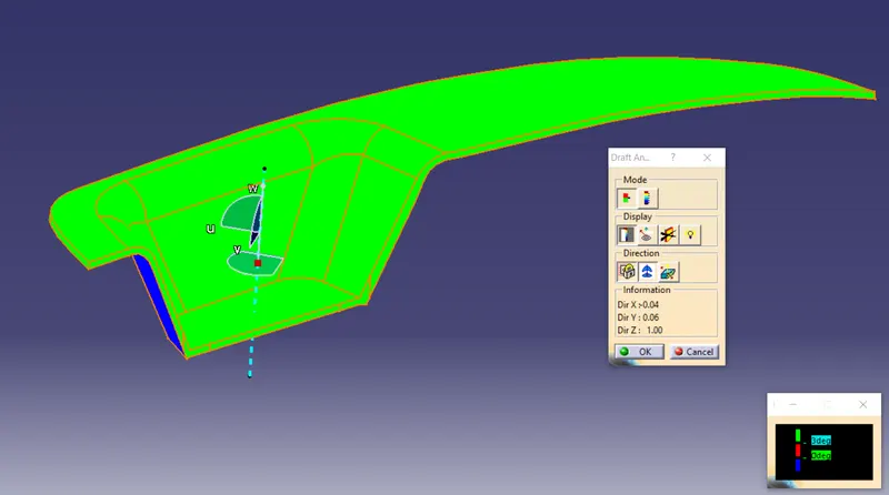
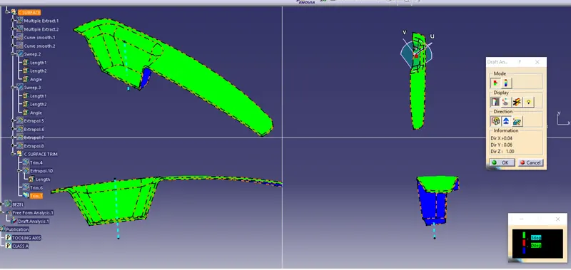
Then I will go insert and select the analysis and in the analysis, I will select the draft analysis. The draft analysis block is shown below
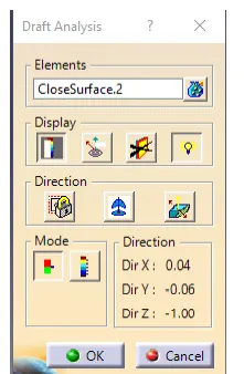
In the above fig. under the display, section selects the color scale and turn on the light effect for proper visualization. then under the direction section, i will click on
the compass and will drag the compass from vehicle zero to my tooling axis. and then I will click on the lock feature and will select the class a surface. The result is
shown below: