Week 8 - Challenge 3 - Switch Bezel Design
DRAFT ANALYSIS:
The Draft Analysis command enables you to detect if the part you drafted will be easily removed. This type of analysis is performed based on color ranges identifying zones on the analyzed element where the deviation from the draft direction at any point, corresponds to specified values.
DRAFT ANALYSIS OF SWITCH BEZEL:
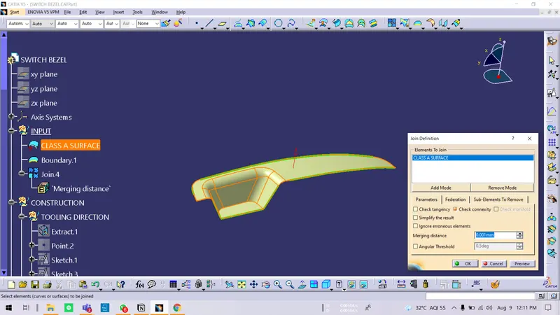
Insert a class A surface model of Switch Bezel in CATIA V5 Surface workbench. Before Starting an exercise. We need to check the connectivity of Class A. SO use the Join command and check how well it is connected. We have to ensure that there are no surface gaps between the faces of the components. This can be done by another method also by using the Boundary command.
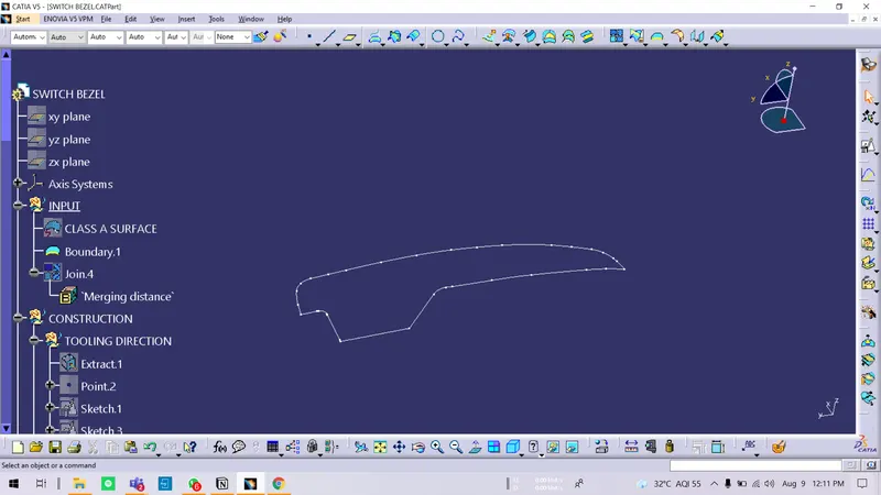
TOOLING AXIS DETERMINATION:
Once this is done and We ensured the continuity of components, the next step is to Find the Best possible Tooling Axis. (Tooling axis is a direction in which mold / core-Cavity opens. So analyze the component and by analysis, we find Z direction as the best possible tooling axis for the Base Bracket as we can manufacture all faces and holes in the component.
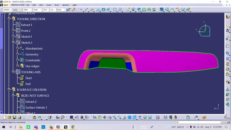
- Decide Tooling Direction
Insert Geo set ( Tooling Direction) -construction
- Clearing Y direction:
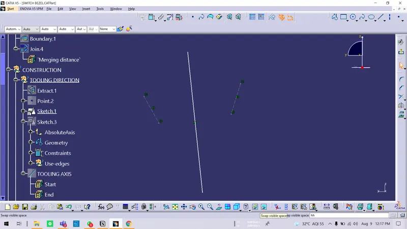
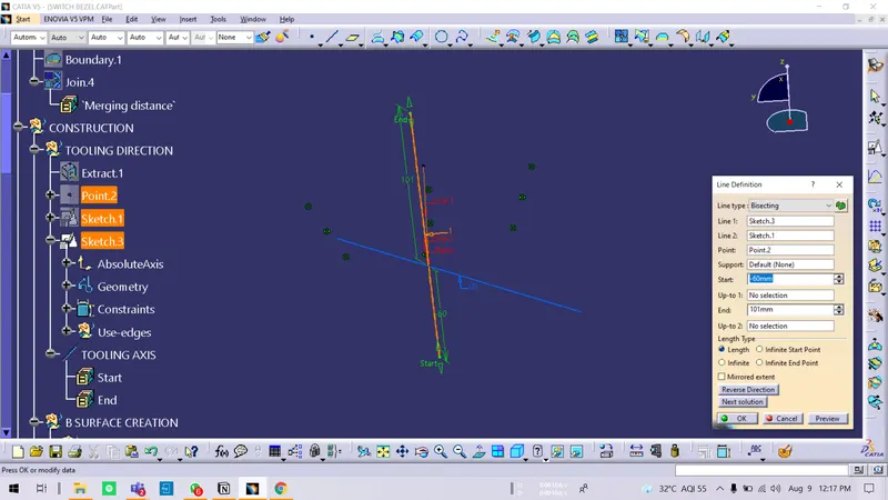
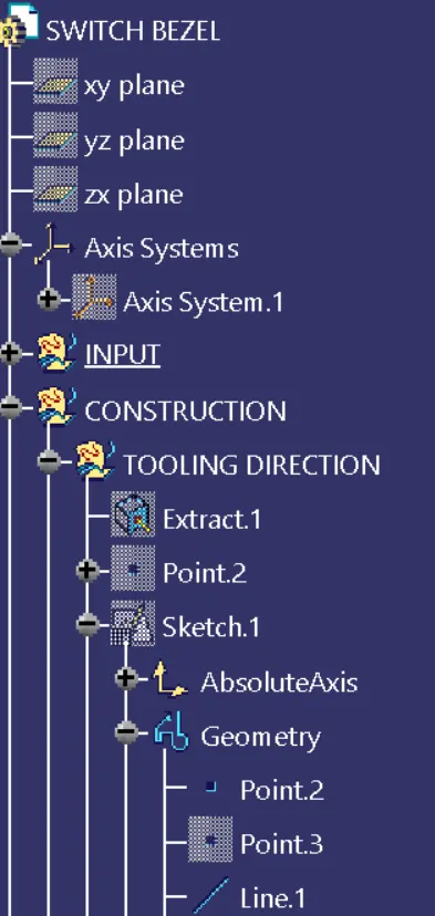
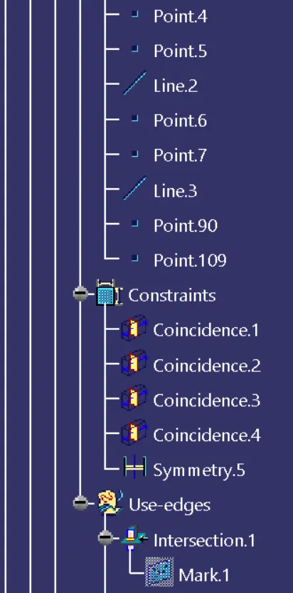
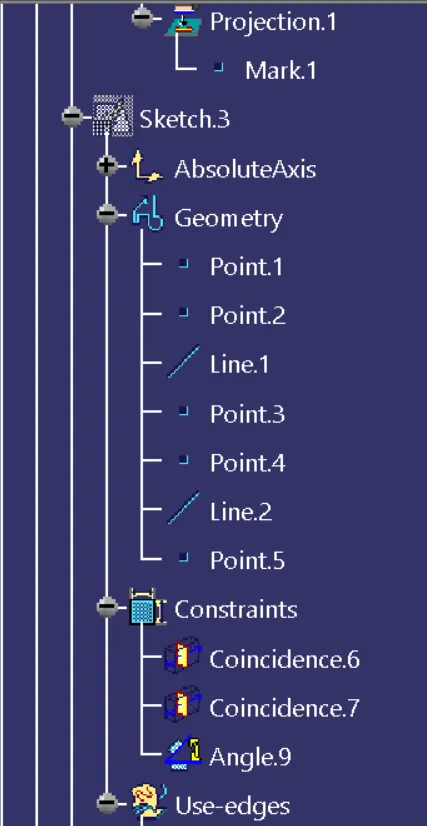
Create Planes on the surfaces - Extract the base surface, Create point over it, Insert Axis System, Positioned Sketch, Projections, Draw lines along the walls, hide reference, keep projection of point, Bisecting Line, Trim it to requirement, Convert wall lines into construction, keep the only bisecting line
- Clearing X direction:
Positioned sketch, ZX PLane, Cut section, Projection, Draw lines along the wall, Draw another line at center with 4 or tries 6-degree tooling axis with 1st line, Keep only 2nd line, rest turn into construction.
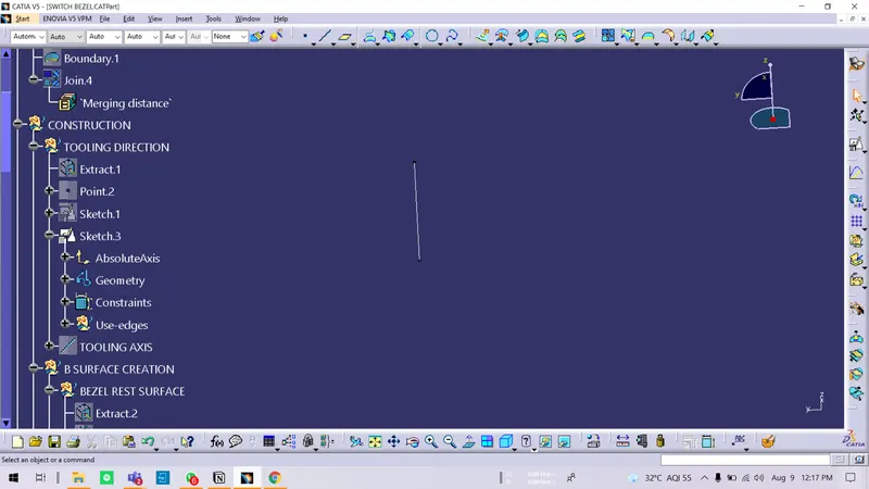
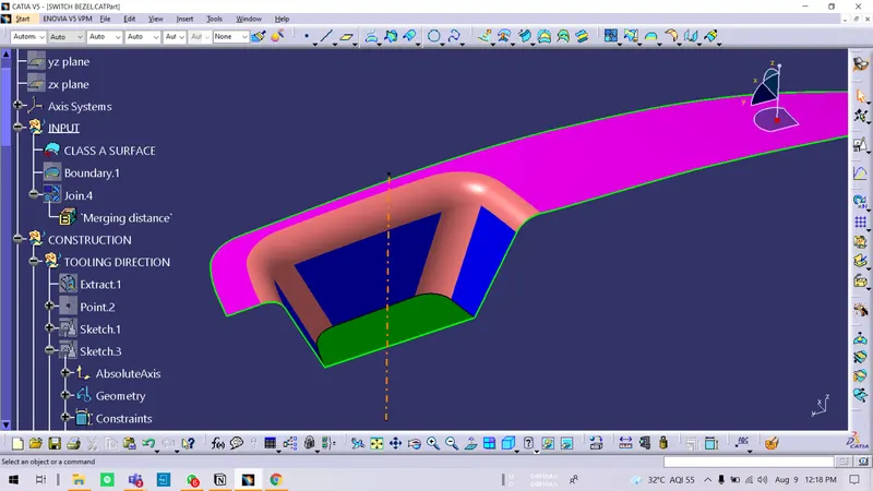
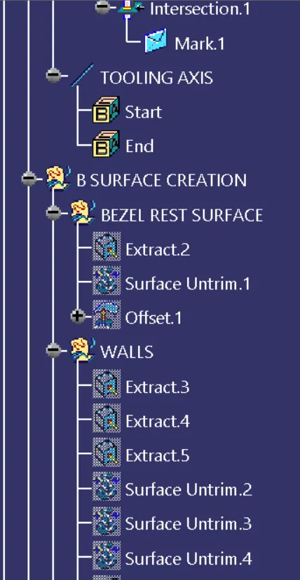
- Now we have 2 lines - bisect them, Hide everything, got the Tooling Axis. Extend. Name it Tooling Axis. Colour, Type. Publish. Also, Class A publish.
When you put the tooling Axis at normal and You can see all the surfaces. It's right.
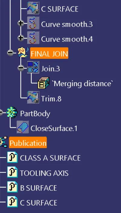
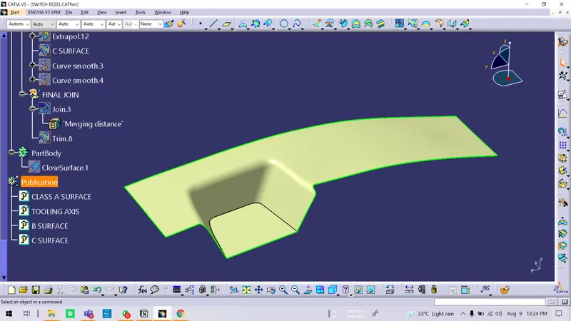
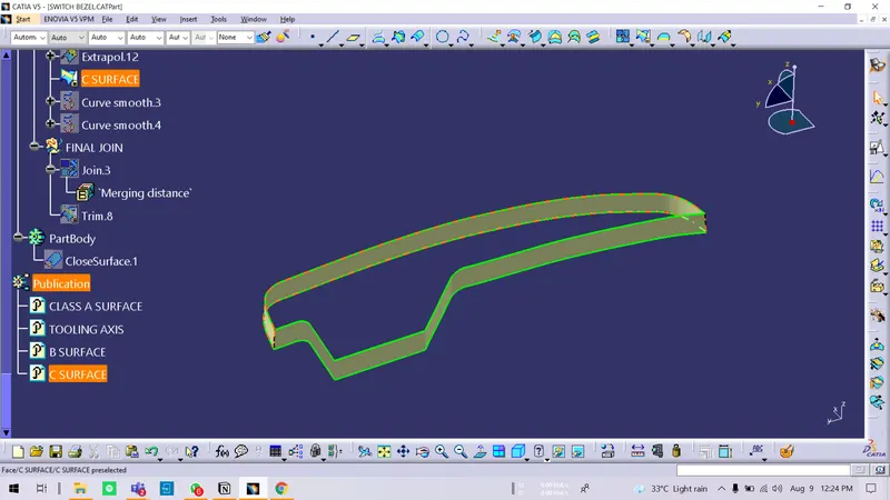
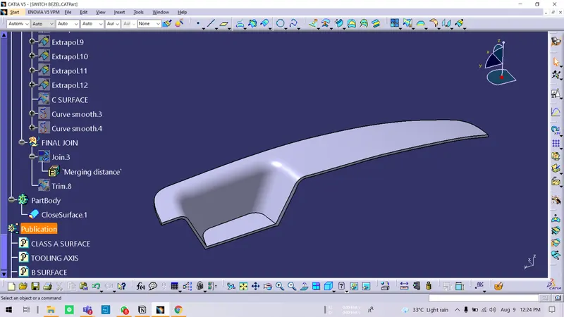
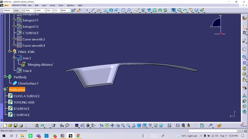
PUBLICATIONS:
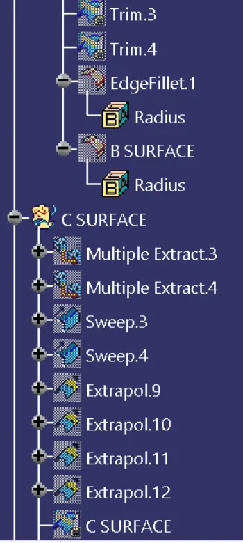
Select Class A surface and Tooling axis, B Surface, C Surface, and go to tools and Publish them. ( We do this for the purpose of easily selecting or picking)
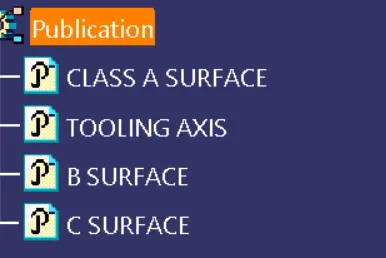
SELECTING MATERIAL:
Go to the toolbar View mode and customize it. Select Material option in Shading column.
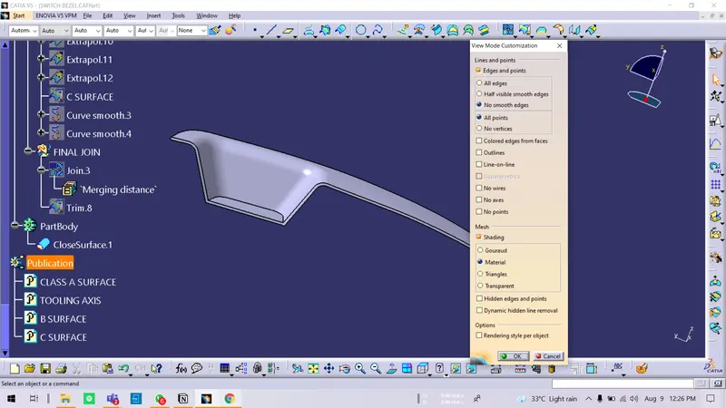
Draft Analysis:
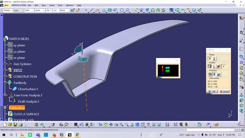
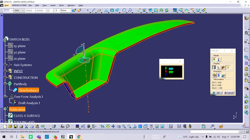
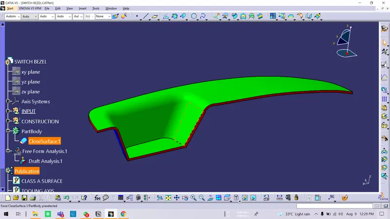
- Draft analysis: Compass Direction, Select redpoint move it to the tooling axis. Lock, Click on component, You see green on one side and blue on the other. Turn Blue to red and red to some other. Give minimum 2.9-degree draft. ( Green)
- Turn light mode on.