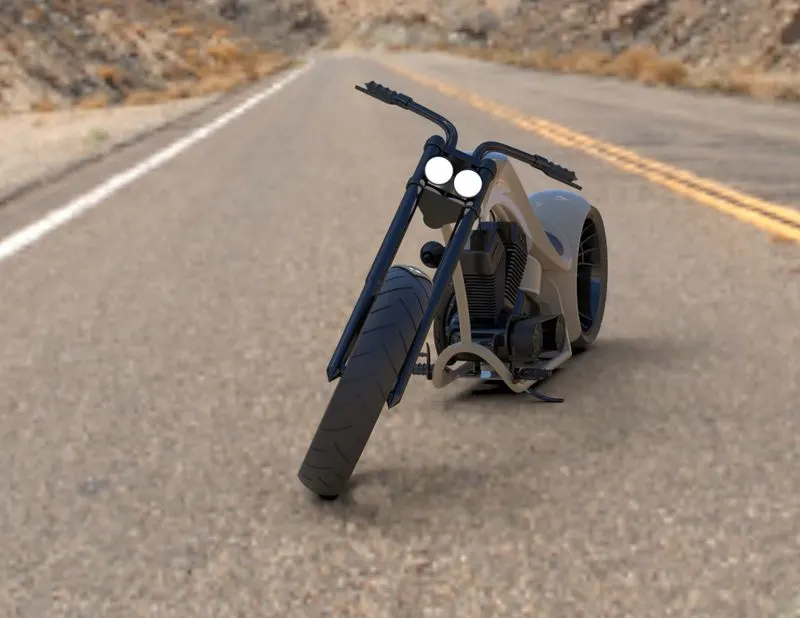
Photo Realistic Rendering
MODELLING OF AMERICAN CHOPPER
OBJECTIVE:
The aim of this project is to sketch and model American chopper bike by designing and modelling different parts of the bike and assembling them together using the software Solidworks.
INTRODUCTION:
Solidworks is 3D modelling CAD and CAE computer program than runs on Microsoft windows. It is created by DASSULT SYSTEMS. Solidworks provide dedicated tools and workflows that streamline the design and development of your product from concepts through to reality. Intelligence is baked into solidworks making it simple to create winning design in record time.
CHOPPER:
Chopper is a type of custom motorcycle which emerged in California in late 1950s. The chopper is perhaps the most extreme of all custom styles, often using radically modified steering angles and lengthened forks for a stretched-out appearance. Some of the characteristics features of chopper are long front ends with extended forks often coupled with an increased rake angle, hardtail frames (Frames without rear suspension), very tall “ape hanger” or very short “drag” handlebars, lengthened or stretched frames, and larger than stock front wheels.
DESIGN METHODOLOGY:

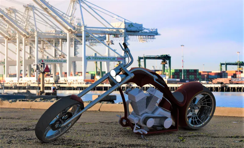
AMERICAN CHOPPER IS THE ASSEMBLY OF FOLLOWING PARTS
- Transmission belt
- kickstand
- Front fender
- Rear fender
- Chain
- Oil tank
- Pedal
- Front wheel
- Rear wheel
- Front fork
- Chassis
- Engine
- Gas tank
DESCRIPTION OF THE PARTS:
1) Transmission belt:
A belt is a loop of flexible material used to link two or more rotating shaft, mechanically, most often parallel. Belts may be used as a source of motion, to transmit power efficiently or to track relative movement. Belts are the cheapest utility for power transmission between shafts that may not be axially aligned. Power transmission is achieved by purposely designed belts and pulleys.
- Sketch tools : Sketching geometry (line, arc, offset entities)
- Feature tools : Extrude Boss/Base, Fillets
- Appearance : Matte Rubber
- Rendering : Photo view 360
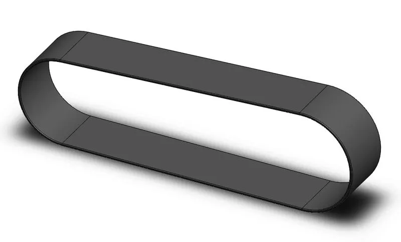
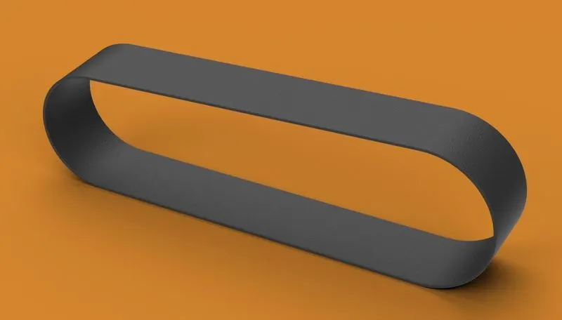
Procedure:
- Start the sketch on front plane. Draw the required sketch with proper dimensions.
- Create outside sketch by using “Offset entities” sketch tool. Give proper offset value.
- Create Boss extrude by selecting proper options and giving proper distance value.
- Apply Fillets to the edges by selecting diameter values as required.
- Apply Matte rubber appearance to the whole part.
- Render image by using photoview 360.
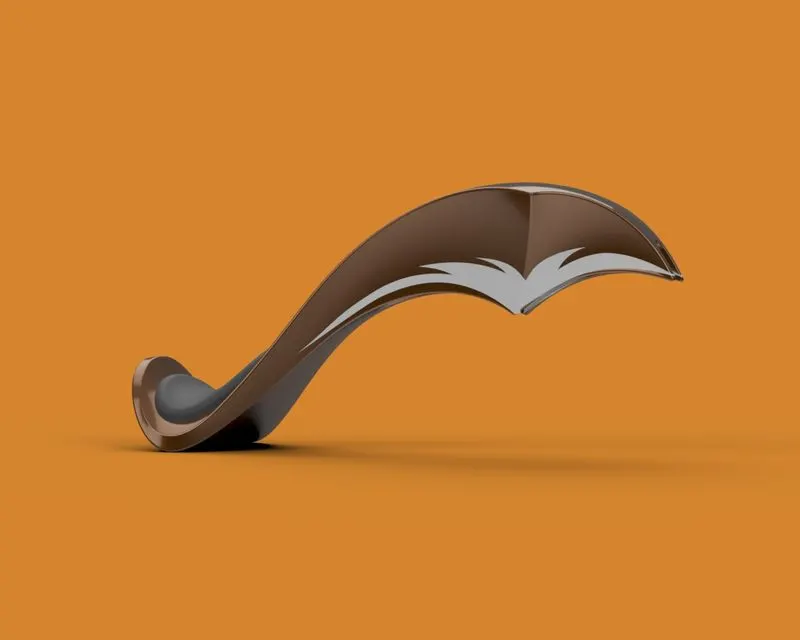
2) Kickstand:
Kickstand is a device on a motorcycle that allows the bike to be kept upright without leaning against another object or the aid of a person. A side stand style Kickstand is a single leg that simply flips out to one side, usually the left side, and the bike then leans against it.
- Sketch tools : Sketching geometry (line, circle, 3-point arc, ellipse, spline)
- Feature tools : Lofted Boss/Base extrude, Dome, Extrude-cut, split, Fillets
- Appearance : Chrome steel
- Rendering : Photo view 360
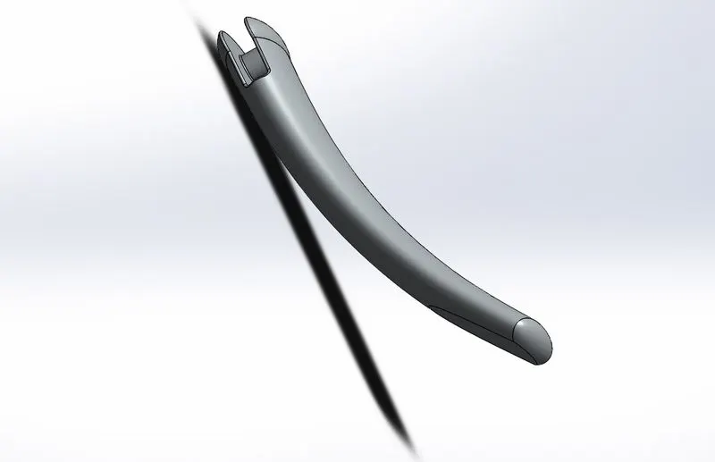
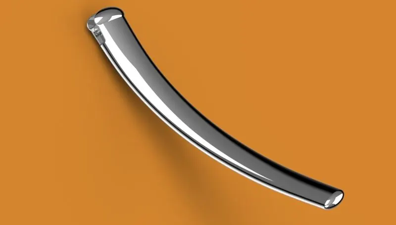
Procedure:
- Start sketching on front plane. Draw an ellipse from the origin. Apply proper dimensions.
- Start a sketch on midplane. Draw a spline from the origin. Apply proper dimensions by activating upper handle and lower handles.
- Create a new plane normal to the spline at the end point of the spline. Start sketch on new plane by drawing an ellipse at the origin. Apply proper dimensions. Create lofted boss/base by selecting two ellipses as profiles and spline as a centreline parameter.
- Apply elliptical dome on both faces of the solid body with proper diameter values.
- Draw centre type rectangle on midplane from origin. Do extrude cut by selecting through-all both option.
- Start sketch on plane 1. Create the flat spot by using split tool.
- Draw a circle on top plane and do extrude boss by setting upto next option in both directions.
- Apply fillets to required edges of proper diameter.
- Finally apply chrome plate appearance to the part.
3) Front fender:
Fender is the American English term for the parts of an automobile, motorcycle and other vehicle body that frames a wheel well. Its primary purpose is to prevent sand, mud, rocks, liquids, and other road spray from being thrown into air by the rotating tire. The fender which is used for front wheel is termed as front fender.
- Sketch tools : Sketching geometry (line, spline, 3 point arc, Extend entities, trim entities)
- Feature tools : Revolved boss/base, split and fillets
- Appearance : Painted siena
- Rendering : Photo view 360
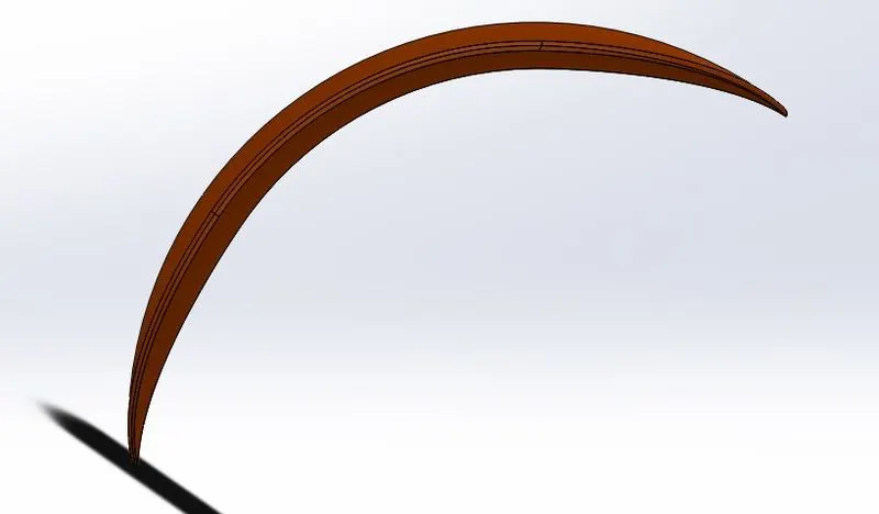
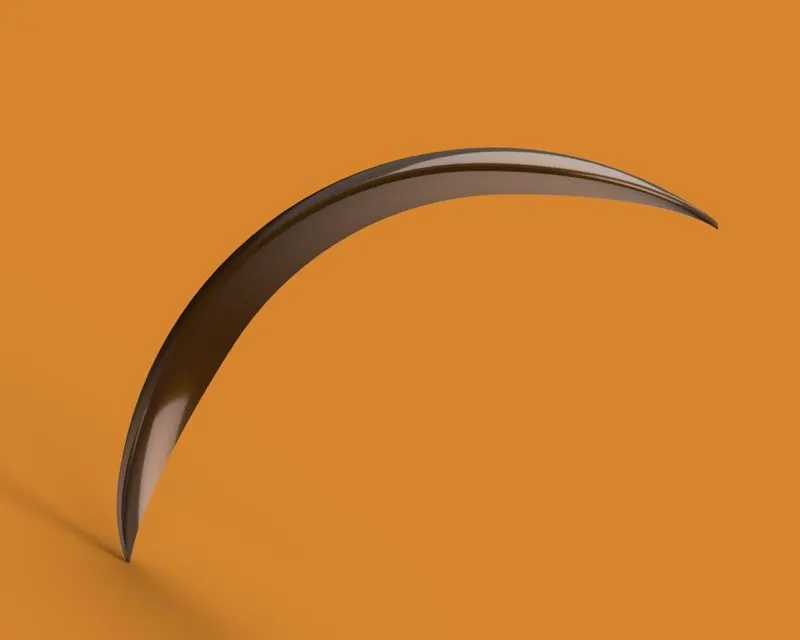
Procedure:
- Start sketch on vertical plane front fender. Draw the sketch as required by using 3 point arc tool, offset entities and extend entities.
- Create an axis of revolution. Create revolved boss/base by using direction 1 and direction 2 functionality.
- Draw the two mirrored splines on center plane front plane with proper dimensions. Use split tool to cut the parts that we don’t need.
- Start new sketch on vertical plane front fender, keep the required side at the bottom. Draw the mirrored splines with proper dimensions. Use split tool to cut required parts.
- Apply fillets to required edges with proper diameter value.
- Apply painted car siena appearance to the front fender.
4) Rear fender:
Fender is the American English term for the parts of an automobile, motorcycle and other vehicle body that frames a wheel well. Its primary purpose is to prevent sand, mud, rocks, liquids, and other road spray from being thrown into air by the rotating tire. The fender which is used for rear wheel is termed as rear fender.
- Sketch tools : Sketching geometry (line, spline, 3 point arc, Extend entities, trim entities)
- Feature tools : Revolved boss/base, split and fillets
- Appearance : Painted siena
- Rendering : Photo view 360
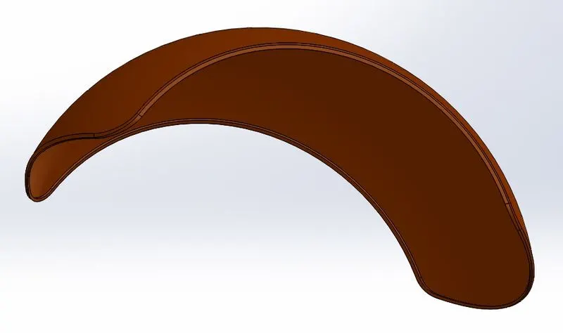
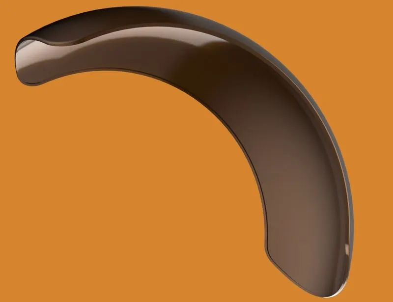
Procedure:
- Start sketch on vertical plane front fender. Draw the sketch as required by using 3 point arc tool, offset entities and extend entities.
- Create an axis of revolution. Create revolved boss/base by using direction 1 and direction 2 functionality.
- Draw the two mirrored splines on center plane front plane with proper dimensions. Use split tool to cut the parts that we don’t need.
- Start new sketch on vertical plane front fender, keep the required side at the bottom. Draw the mirrored splines with proper dimensions. Use split tool to cut required parts.
- Apply fillets to required edges with proper diameter value.
- Apply painted car siena appearance to the rear fender.
5) Chain:
Chain is most commonly used for transmission of mechanical power. It consists of a series of short cylindrical rollers held together by side links. It is driven by toothed wheel called a sprocket. It is a simple, reliable and efficient means of power transmission.
- Sketch tools : Sketching geometry (line, circle, straight slots and 3 point arc)
- Feature tools : Extruded boss/base, curve driven pattern, mirror, blocks, fillets
- Appearance : Chrome steel
- Rendering : Photo view 360
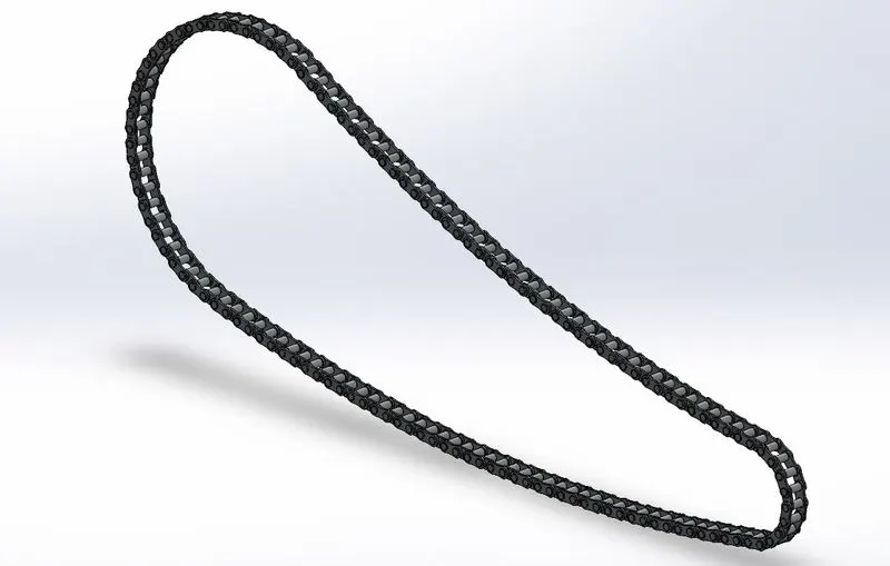
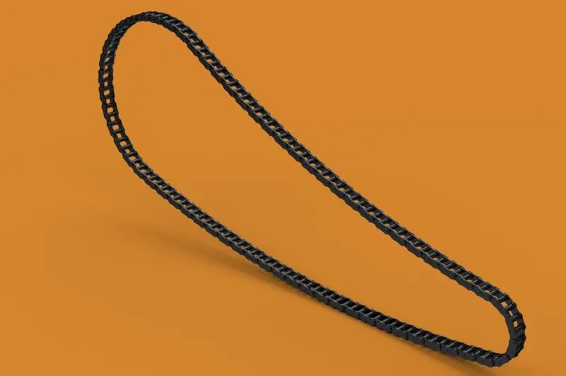
Procedure:
- Start sketching on midplane. Draw the path of chain by using line, circle and 3 point arc with proper dimensions.
- Draw the chain link 1 and chain link 2 and save them seperatly by adding blocks.
- Go to insert block and bring those blocks into sketch
- Place the two links as required at desired location. Extrude both the links in proper way.
- Apply fillets with proper diameter values.
- Replicate the links by using curve driven pattern. Make sure the pattern perfectly follows original chain path.
- Make adjustments at the end (if needed).
- Mirror the link plates across the midplane.
- Apply chrome plate appearance to the chain.
6) Oil tank:
Oil tank is a hollow part which stores oil needed to run Engine.
- Sketch tools : Sketching geometry(line, circle, spline)
- Feature tools : Extruded boss/base, combine, shell, fillets
- Appearance : Painted siena and white painted car
- Rendering : Photo view 360
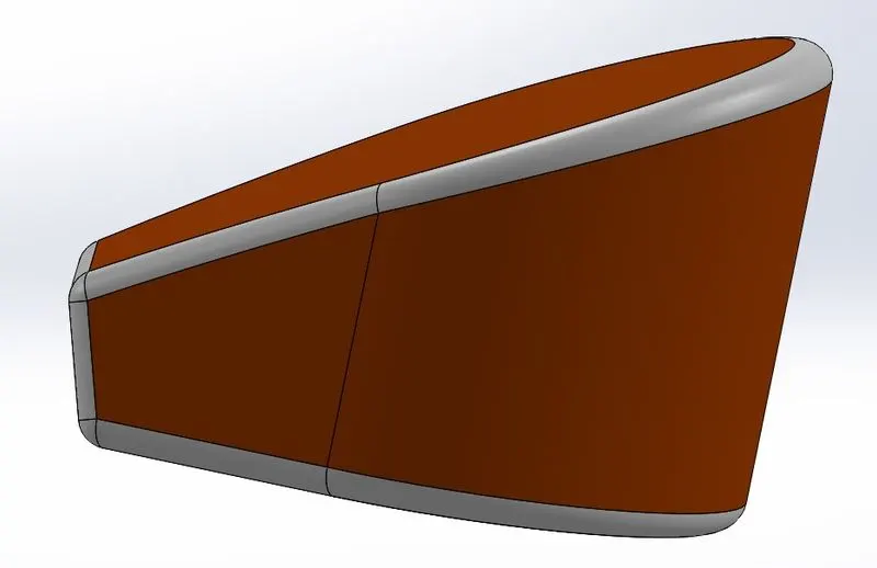
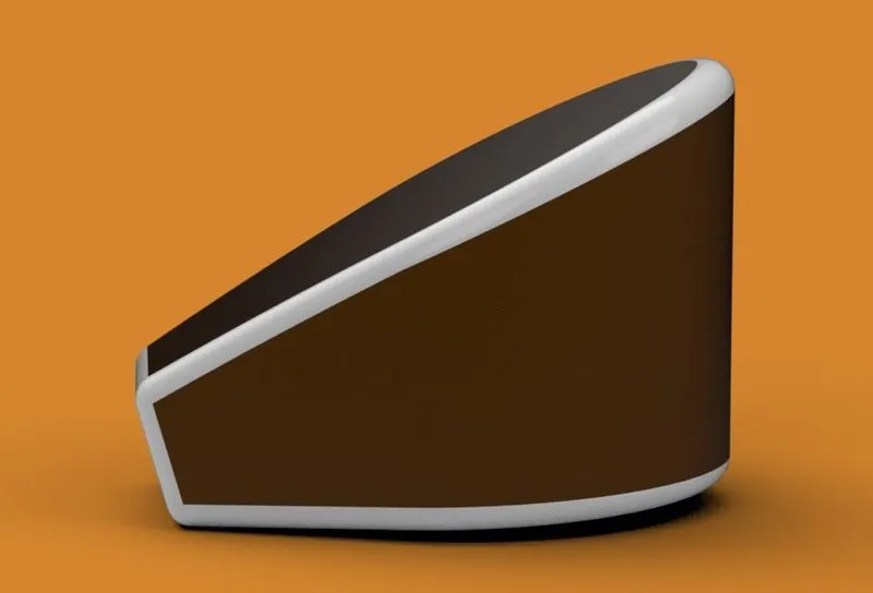
Procedure:
- Start sketch on top plane by drawing lines, 3 point arc, add relations, give proper dimensions. Make sure it is fully defined. Extrude it by using Boss/Base feature.
- Start sketch on midplane by drawing lines and adding proper dimensions. Extrude it by selecting option “through-all” in both directions.
- Combine boss extrude 1 and boss extrude 2.
- Apply fillets. Apply appearance white painted car to the fillets feature.
- Apply Siena appearance to rest of the part.
- Apply Shell of 3mm value.
7) Pedal:
Pedal is the external part attached to the chassis. Its main purpose is to rest foot on it.
- Sketch tools : Sketching geometry (line, circle and spline)
- Feature tools : Revolve boss/base, Extrude boss/base, Dome, linear pattern, chamfer and fillets
- Appearance : Chrome steel
- Rendering : Photo view 360
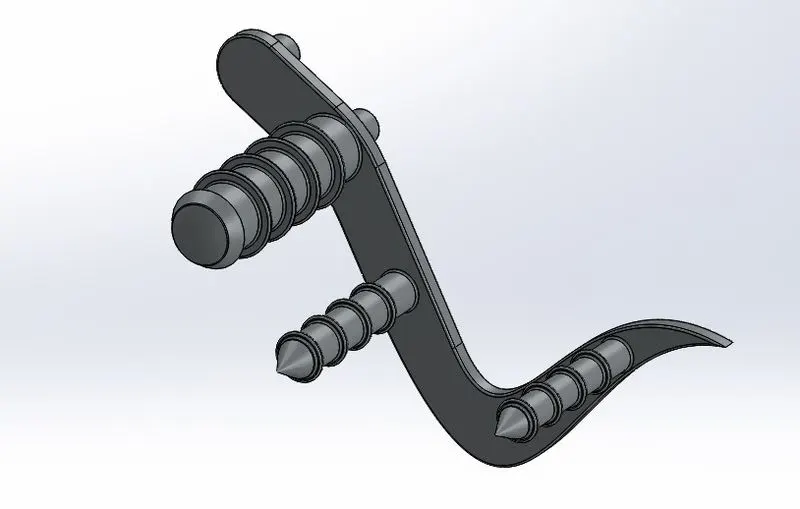
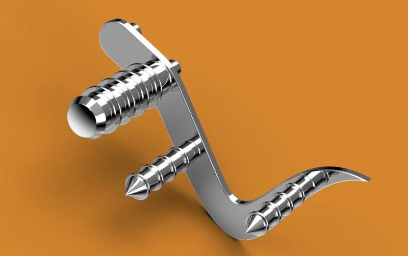
Procedure:
- Start sketch on front plane by drawing line, spline and give proper dimensions in order to make it fully defined.
- Extrude it and apply fillets.
- Start the sketch on front surface on the extruded part by drawing two circles.
- Use a dome circular feature.
- Apply linear pattern to boss extrude and apply distance-distance chamfer to it.
- Give appearance to the part.
8) Front wheel:
Wheels are made to cope with radial and axial forces. They also provide a way of mounting other critical components such as brakes, final drive and suspension. The wheel attached at the front side of the chassis and to the front fork is termed as a front wheel.
- Sketch tools : Sketching geometry (line, 3 point arc, circle, spline, Rectangle, offset entities, trim entities, convert entities, extend entities
- Feature tools : Revolved boss/base, Extruded boss/base, revolved cut, circular pattern, combine, mirror, chamfer, fillet
- Solid Bodies : Rim, rotor, caliper and tire
- Appearance : Chrome steel (Rim), carbon steel (rotor), siena (caliper), Matte rubber (tire)
- Rendering : Photo view 360

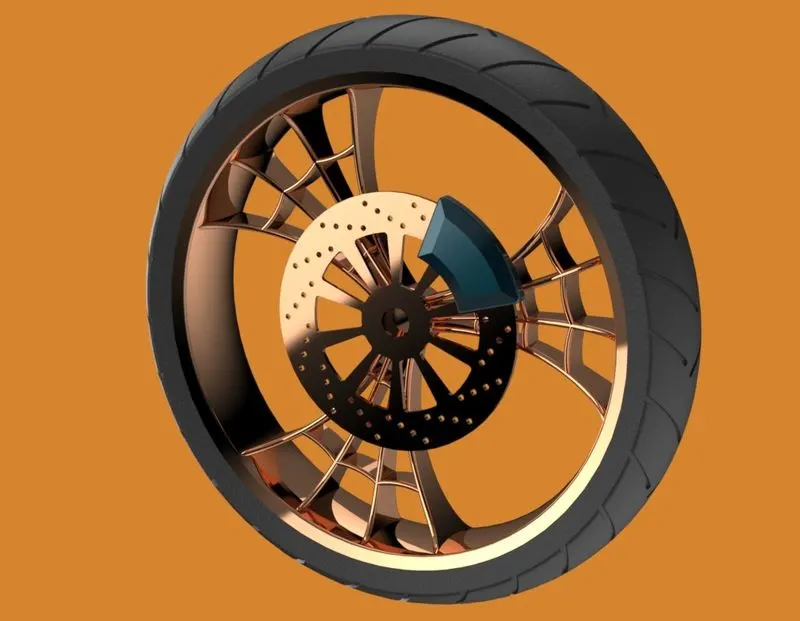
Procedure:
- Sketch the rim and do revolved boss with proper dimensions applied.
- Create spider webbed design in the rim and with the help of circular patterns make 3 instances of it. Add proper fillets.
- Draw the sketch for rotor and extrude it. Draw the circles on the rotor and by using circular pattern and linear pattern create a design.
- Draw the sketch for caliper and extrude it. Apply chamfer of required dimensions.
- Draw the sketch for tire and do revolved boss extrude.
- Create thread pattern on the tire surface by using cut extrude. Create thread pattern for whole tire using circular pattern feature. Apply required fillets to the threads.
- Apply appearance to all four solid bodies.
9) Rear wheel:
Wheels are made to cope with radial and axial forces. They also provide a way of mounting other critical components such as brakes, final drive and suspension. The wheel attached to the rear side of the chassis is termed as a rear wheel.
- Sketch tools : Sketching geometry (line, 3 point arc, circle, spline, Rectangle, offset entities, trim entities, convert entities, extend entities
- Feature tools : Revolved boss/base, Extruded boss/base, revolved cut, circular pattern, combine, mirror, chamfer, fillet
- Solid Bodies : Rim, rotor, caliper, sprocket and tire
- Appearance : Chrome steel (Rim), carbon steel (rotor), siena (caliper), chrome steel (sprocket) Matte rubber (tire)
- Rendering : Photo view 360
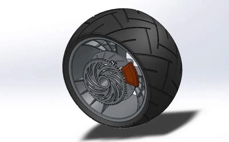
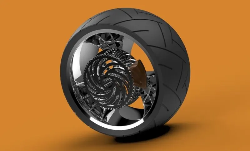
Procedure:
- Sketch the rim and do revolved boss with proper dimensions applied.
- Create spider webbed design in the rim and with the help of circular patterns make 3 instances of it. Add proper fillets.
- Draw the sketch for rotor and extrude it. Draw the circles on the rotor and by using circular pattern and linear pattern create a design.
- Draw the sketch for caliper and extrude it. Apply chamfer of required dimensions.
- Draw a circle for sprocket and extrude it. Apply chamfer to the outer part and create teeth by doing cut extrude. Remove the unwanted portion by cut extruding.
- Draw the sketch for tire and do revolved boss extrude.
- Create thread pattern on the tire surface by using cut extrude. Create thread pattern for whole tire using circular pattern feature. Apply required fillets to the threads.
- Apply appearance to all five solid bodies
10) Front fork:
A fork connects a motorcycle’s front wheel and axle to its frame (chassis), typically via a yoke, also known as triple clamp, which consists of an upper yoke joined to a lower yoke via a steering stem, a shaft that runs through the steering head, creating the steering axis. Most forks incorporate the front suspension and front brake, and allow the front wheel to rotate about the steering axis so that the bike may be steered.
- Sketch tools : Sketching geometry (line, spline, circle, convert entities and trim entities)
- Feature tools : Extrude boss/base, extrude cut, dome, revolved cut, projected curve, swept boss/base, combine, mirror and fillets.
- Appearance : Chrome steel (fork), Matte rubber (Handle grip and brake wires)
- Rendering : Photo view 360
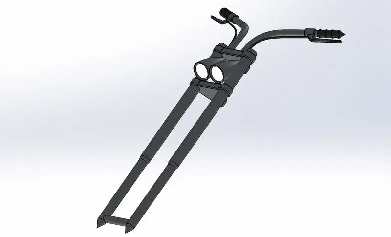
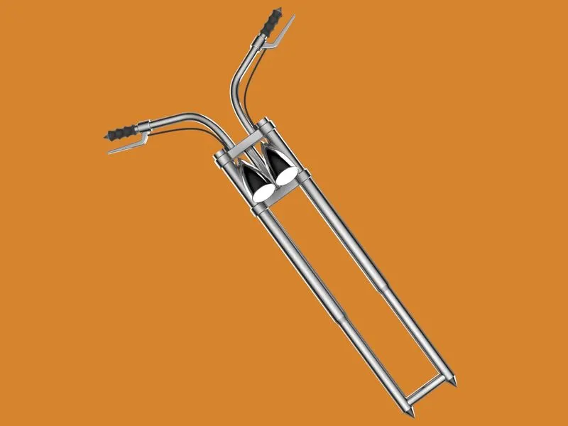
Procedure:
- Start sketch on front plane. Draw the cylindrical sketch for fork tube. Give dimensions and add relation to make it fully defined. Revolve it.
- Select top plane. Draw a sketch by drawing concentric circles for the triple clamps. Give dimensions and add relation to make it fully defined. Extrude it.
- Draw a sketch on front plane by using line, spline for bulb and then revolve it. Move the bulb in z direction. Apply fillets with proper diameter value.
- Select top plane, draw a horizontal construction line, spline for Handle and brake wires. Give dimensions to make it fully defined. Draw a circle normal to the spline and at the end of the spline. Swept along the path of the spline.
- Select the bodies, mirror it and combine it.
- Give appearance to the front fork.
11) Chassis:
Chassis is the load bearing framework of an artificial object, which structurally supports the object in its construction and function. An example of chassis is a vehicle frame, the underpart of a motor vehicle, on which the body is mounted; if the running gears such as wheels and transmission, and sometimes even a driver’s seat, are included, then the assembly is described as rolling chassis.
- Sketch tools : Sketching geometry (line, spline, circle, 3-point arc, convert entities and convert entities)
- Feature tools : Extruded boss/base, extruded cut, dome, split, projected curve, swept boss/base, combine, revolved boss/base, chamfer, mirror and fillet.
- Appearance : Painted siena
- Rendering : Photo view 360
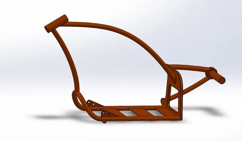
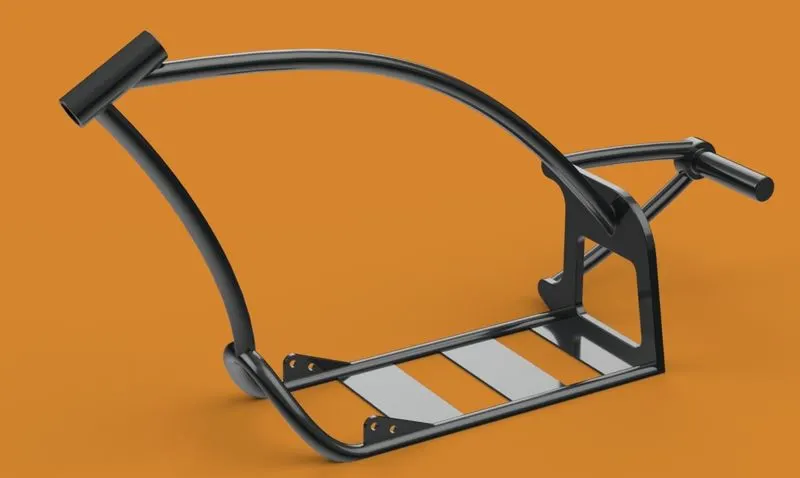
Procedure:
- Insert blueprint of chopper on the front plane. Start sketch on it.
- Draw two concentric circles with the required offset value. Draw horizontal and vertical line from the origin. Draw the spline from center of the circle to the tangent to the horizontal line.
- Start sketch on top plane. Draw the required sketch with proper dimensions and make it fully defined.
- Remove the unwanted area using cut extrude feature. Mirror the bodies and then combine them.
- Apply Fillets and chamfer with required values
- Apply Appearance to the chassis.
12) Engine:
An engine or motor is a machine designed to convert one form of energy into mechanical energy. Motorcycle engine is an engine that powers a motorcycle. Motorcycle engines are typically two-stroke or four-stroke internal combustion engine. Engine is the heart of motorcycle.
- Sketch tools : Sketching geometry (line, spline, circle, 3-point arc, convert entities and convert entities)
- Feature tools : Extruded boss/base, extruded cut, dome, split, projected curve, composite curve swept boss/base, combine, circular pattern, revolved boss/base, chamfer, mirror and fillet.
- Appearance : Chrome steel
- Rendering : Photo view 360
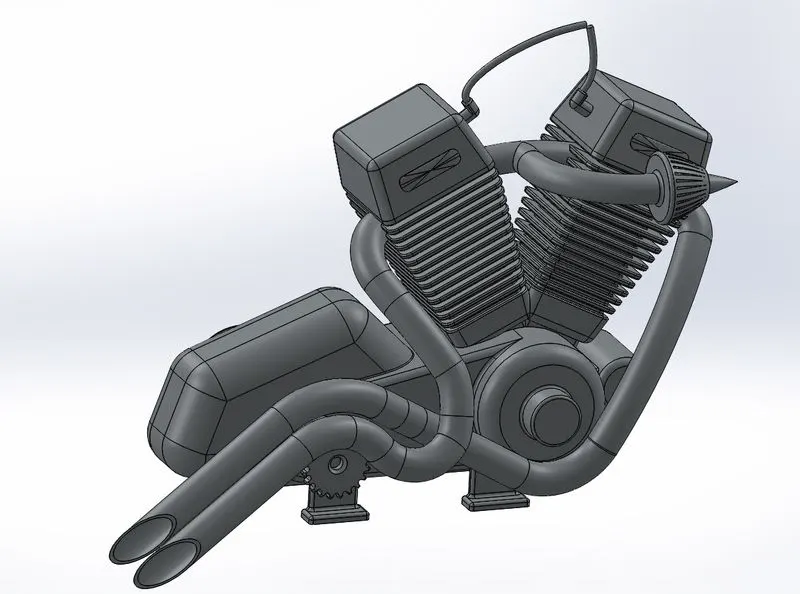
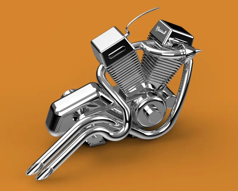
Procedure:
- Insert blueprint of chopper on the front plane. Start sketch on it.
- Draw the sketch for base of engine on front plane and extrude it.
- Draw the sketch for pully, turn on temporary axis and revolve it.
- Draw the rectangle on the pully, extrude it towards outside up to next surface. Select the sketch and make circular pattern.
- Select the outer face of the pully and start sketch on it. Use cut extrude feature to remove unwanted material.
- Draw the sketch on front plane to create cylindrical part of the engine. Give proper dimensions to make it fully defined. Create an angle rectangle to the new plane and do cut extrude.
- Draw two curves. Use the projected curve feature and pierce relation. Swept it.
- Apply appearance to the engine.
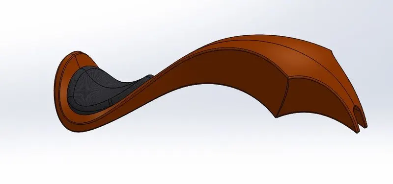
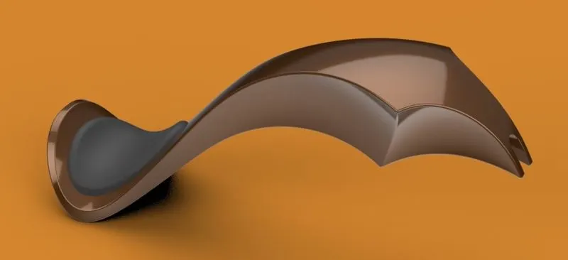
13) Gas tank:
It is a storage tank in which the fuel required for the engine is stored.
- Sketch tools : Sketching geometry (line, spline, circle, convert entities and offset entities)
- Feature tools : Swept surface, lofted surface, boundary surface, Projected curve, knit surface, sweep cut, combine, shell, mirror and fillets.
- Appearance : Painted siena (gas tank), Fabric (driver’s seat)
- Rendering : Photo view 360
Procedure:
- Insert blueprint of chopper on the front plane. Start sketch on it. Draw required sketch with proper dimensions.
- Create a plane at the end point of the spline. Draw another spline and make pierce relation with sketch 1. Sweep it.
- Start sketching on top plane using line, spline. Remove outside portion by using trim entities.
- Create new plane using front plane and end point of surface 2 as a reference. Draw the required sketch on it.
- Draw two sketches on front plane and midplane. Then project the curve and use lofted surface.
- Do the same for completion of the sketch. Mirror it and and apply knit surface.
- Draw the sketch for driver’s seat. Extrude it and apply proper fillets.
- Remove unwanted surface using swept cut and apply shell to the body.
- Give appearance to the tank as well as driver’s seat.
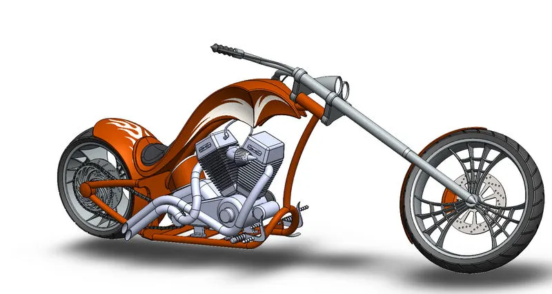
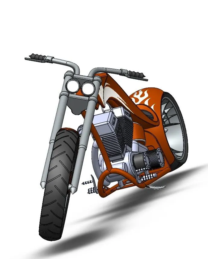
Assembly of designed components:
Step 1 : Insert all files of different parts one by one as per the requirement.
Step 2 : Apply proper mates between different parts in order to get proper alignment.
Step 3 : Apply tangent mate to front wheel, rear wheel and kickstand with top plane to snap it to the floor.
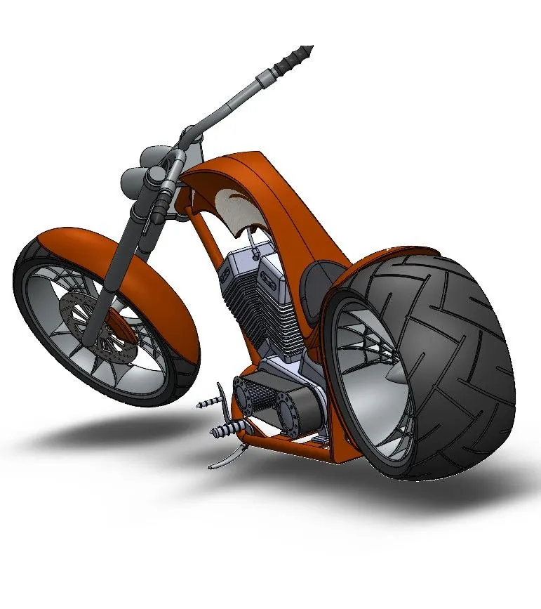
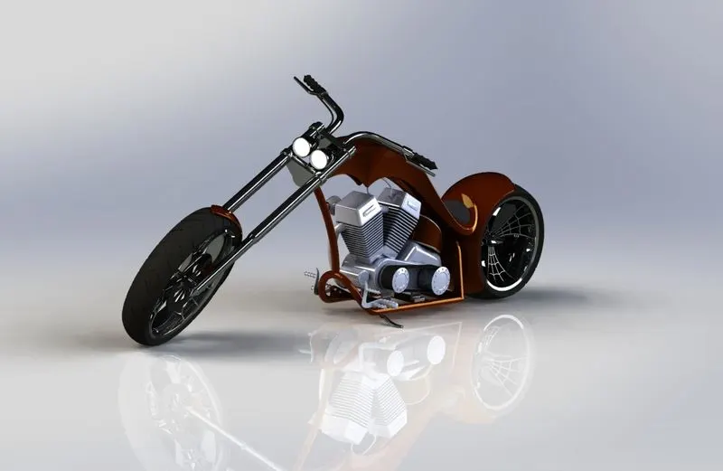
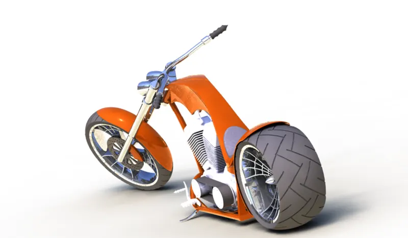
Render image photo view 360:
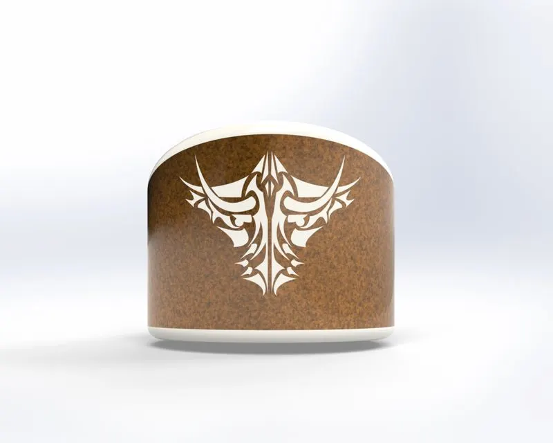
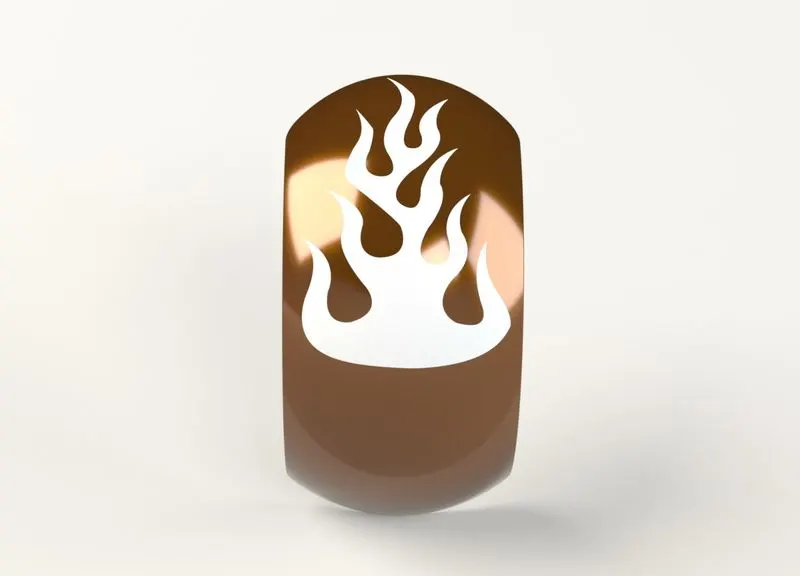
Applying decals, camera setup and scenes:
In this part decals are applied to gas tank, oil tank and rear fender.
Camera setup:
Camera setup is essential for final rendering to get realistic view of chopper.
Scenes and lights:
Add proper scenes and light set-up to make final render more realistic.
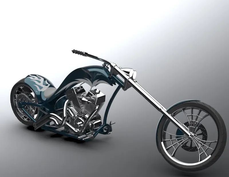
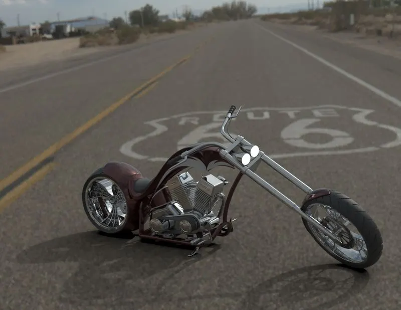
Final render:
In this, we are going to render the chopper to make it realistic.
Software used: Solidworks visualize
Steps to follow:
- Import: Import the assembly file into the solidworks visualize software.
- Appearance: Apply/change appearance to the part.
- Scenes: Add scenes, Enviornment-3D/Plate-2D as a background.
- Output: Make a fast render and once satisfied with the result go for final quality render.
Conclusion:
In this project, each and every part of American chopper model is designed individually as a part file and then assembled together to complete the model. Additional appearance, scenes, decals, camera set-up, light set-up etc. given to make it more realistic. Finally rendered by placing our model in proper environment/background.