Week 8 - Challenge 1 - Draft Analysis on a Fan Cover
DRAFT ANALYSIS:
The Draft Analysis command enables you to detect if the part you drafted will be easily removed. This type of analysis is performed based on color ranges identifying zones on the analyzed element where the deviation from the draft direction at any point, corresponds to specified values.
DRAFT ANALYSIS OF FAN COVER:
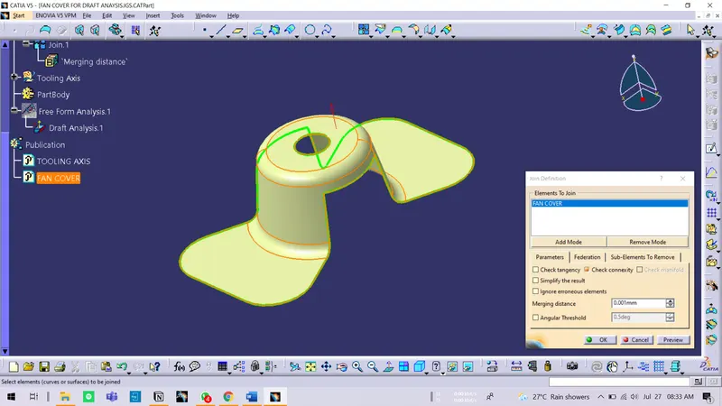
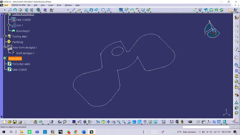
Insert a class A surface model of Fan cover in CATIA V5 Surface workbench. Before Starting an exercise. We need to check the connectivity of Class A. SO use the Join command and check how well it is connected. We have to ensure that there are no surface gaps between the faces of the components. This can be done by another method also by using the Boundary command.
TOOLING AXIS DETERMINATION:
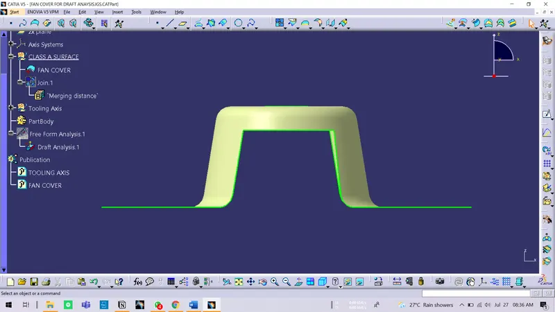
Once this is done and We ensured the continuity of components. The next step is to Find the Best possible Tooling Axis. (Tooling axis is a direction in which mold / core-Cavity opens. So analyze the component and by analysis, we find Z direction as the best possible tooling axis for the Fan cover as we can manufacture all faces and holes in the component.
CLEARING X DIRECTION:
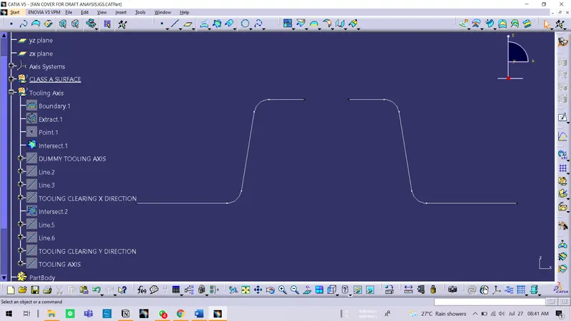
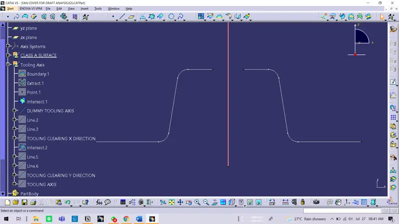
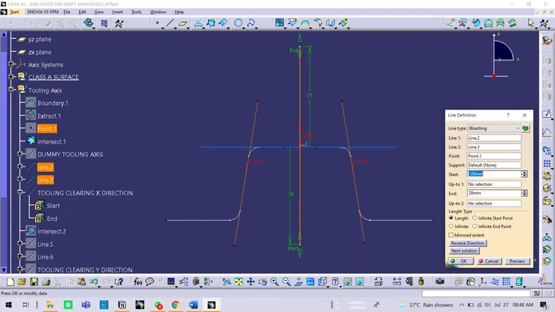
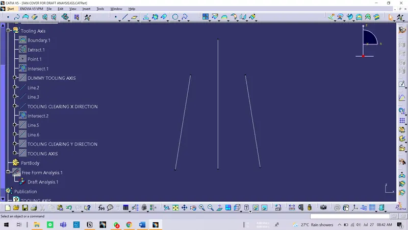
We have decided the tooling axis and now we need to check and ensure that all the faces can be manufactured. So create a geometrical Set and name it as a TOOLING AXIS. Select the inner boundary and create a point using point type- circle/sphere/ ellipse. Z is the tooling axis so we will draw lines along the X and Y directions. Insert an Axis system at the point and ensure that the current option is not selected. Then Take a ZX plane and intersect with the component using intersect command. We get the two curves representing the faces of the component. Draw a line along Z-axis through the point using line type- point direction. Name it as a DUMMY TOOLING AXIS. Then analyze which faces can be easily cleared and which faces can have some trouble. Cross-check for the faces that can cause some trouble. So create two lines representing the two faces which can cause an error by using line type as point-point. Now create a bisecting line by using references as line 1 line 2 and point. The Red colored line represents the direction of the bisecting line. Click on the required direction. The bisecting line follows the direction of our tooling Axis that means we have cleared our check for X direction. So name the line as TOOLING CLEARING X DIRECTION in the feature tree.
CLEARING Y DIRECTION:
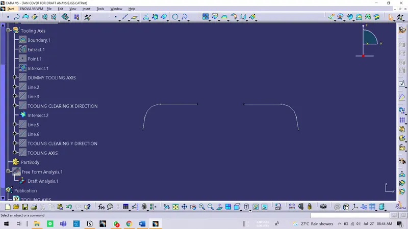
Do the same for the Y direction. Take the same tooling axis, point, and Axis system. Then take the YZ plane and intersect with the component. We get the two curves representing the faces of the component. Select the two lines which might create the error. So create two lines representing the two faces which can cause an error by using line type as point-point. Now create a bisecting line by using references as line 1 line 2 and point. The bisecting line follows the direction of our tooling Axis that means we have cleared our check for the Y direction. So name the line as TOOLING CLEARING Y DIRECTION in the feature tree.
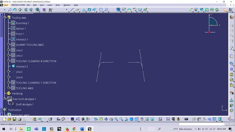
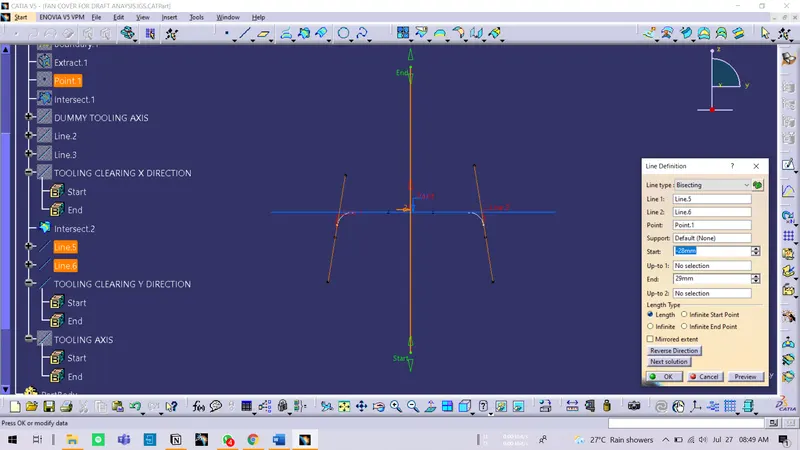
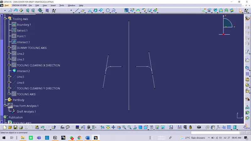
Create Bisecting line using TOOLING CLEARING X DIRECTION, TOOLING CLEARING Y DIRECTION, and point. Hide all the lines and pick the correct direction for bisecting line. Name it as a TOOLING AXIS.
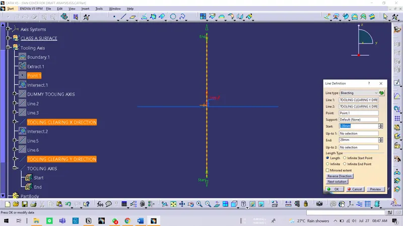
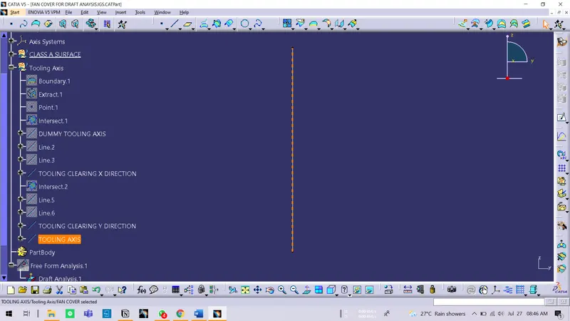
PUBLICATIONS:
Select Fan cover and Tooling axis and go to tools and Publish them. ( We do this for the purpose of easily selecting or picking)
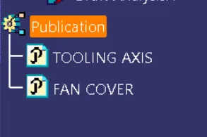
SELECTING MATERIAL:
Go to the toolbar View mode and customize it. Select Material option in Shading column.
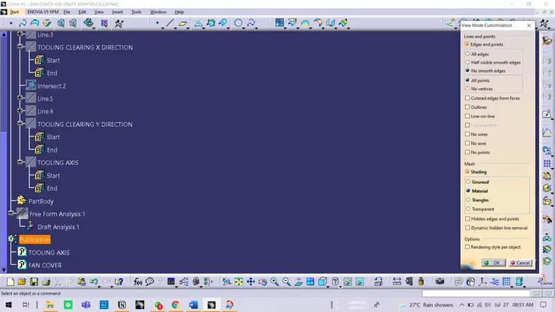
DRAFT ANALYSIS:
Go to Insert -Analysis-Feature Draft Analysis. Use the compass to define the new current draft direction. Hold the red dot on the compass and place it anywhere on the component. Later place it along the tooling axis considering the correct direction. The 'w' of the compass should be in line with the tooling axis. Lock the arrangement.
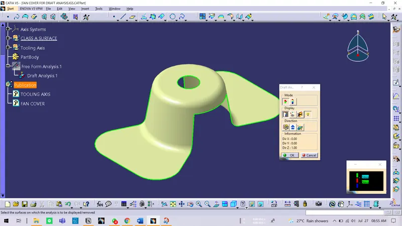
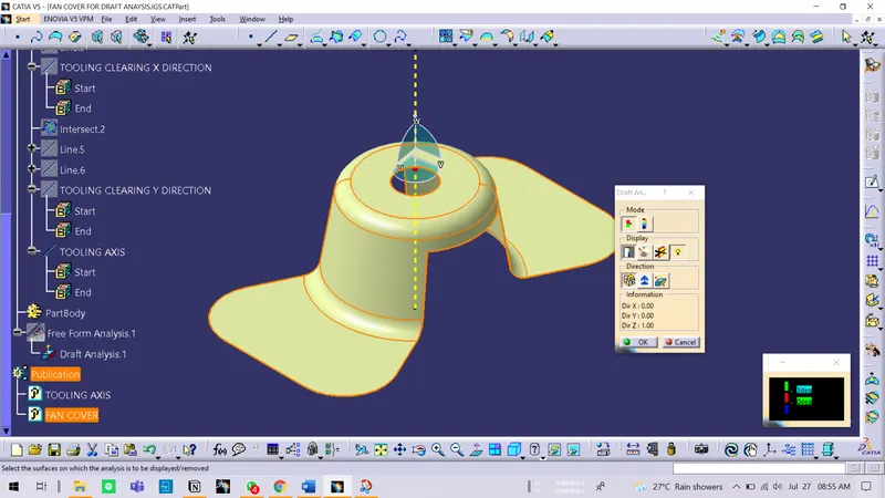
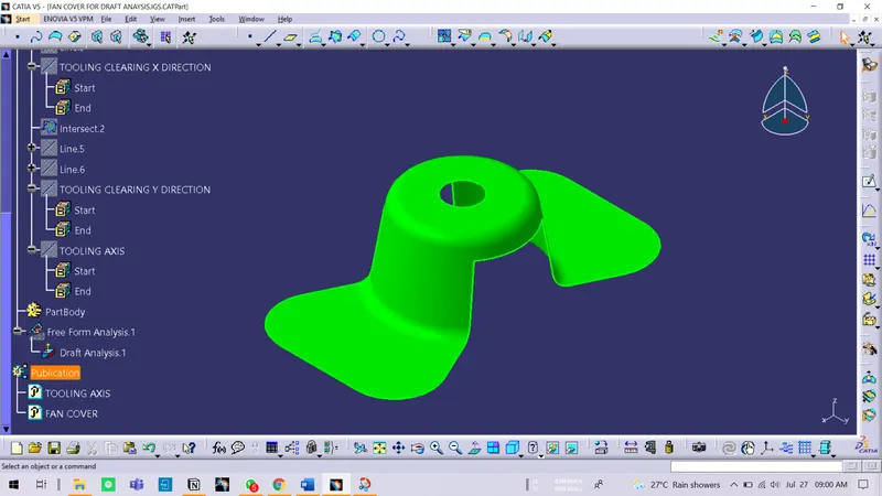
Click on the component. The color of the component changes to green. Look into the color table. It shows green is 2 degrees, Red is in between 0 to 2 degrees and Blue is negative. The minimum draft required for the component is 3 degrees so make green as a 3degrees. So we see even for 3 the component is clearing. Analyze the component using Analyses under the running point command. As the component is green in color it indicates that the component is ready to design.
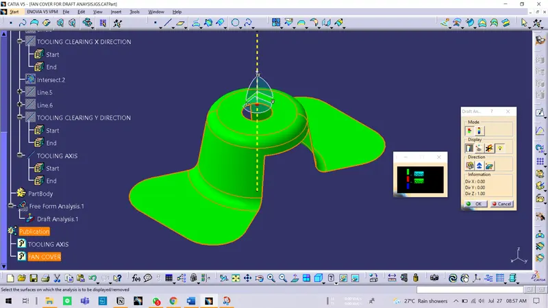
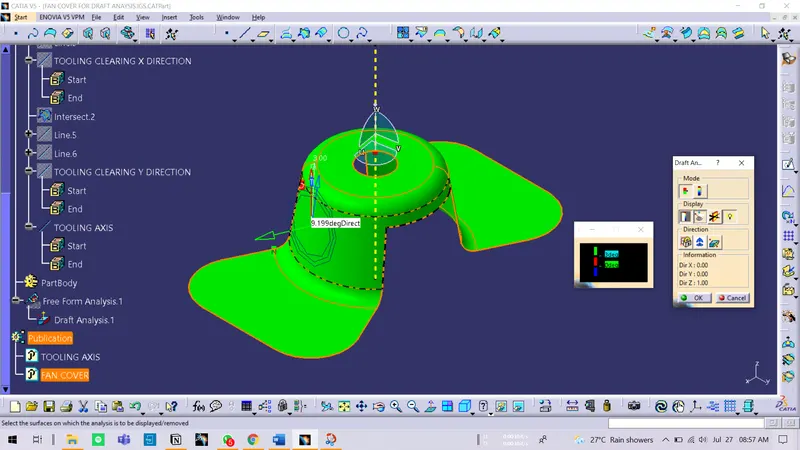
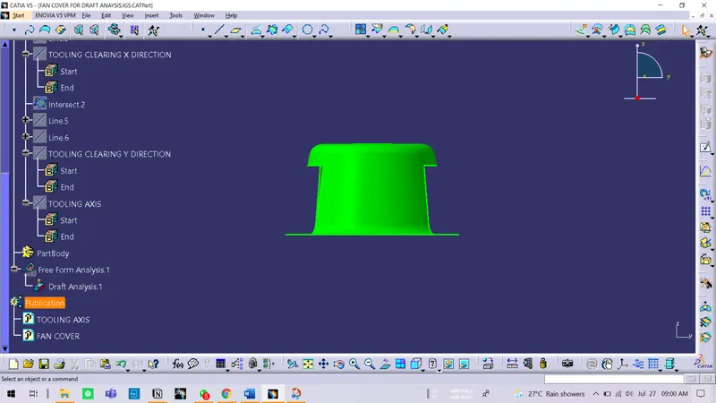
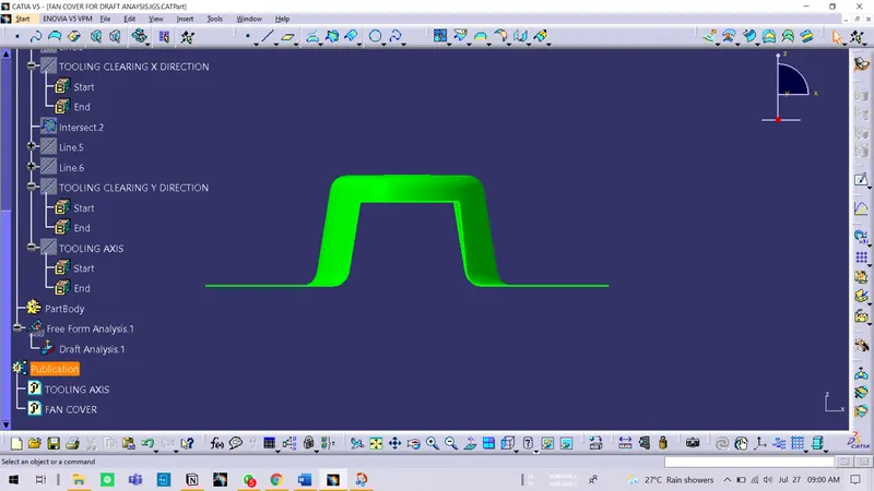
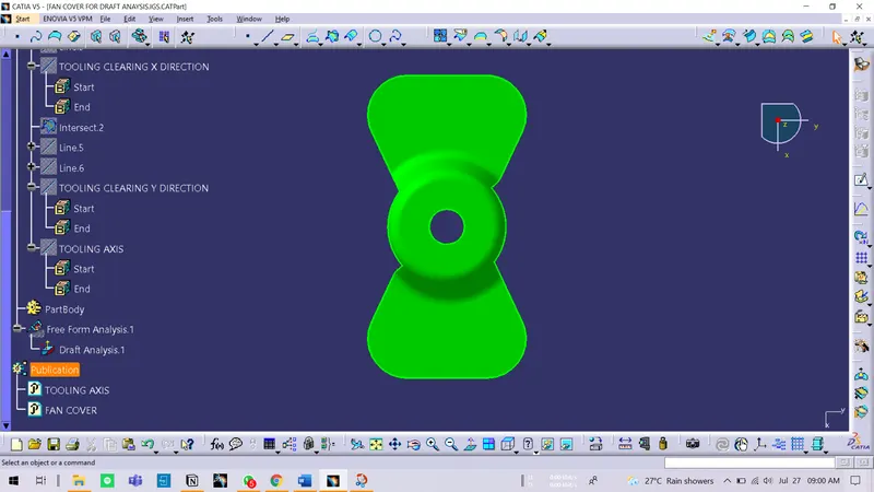
SCREENSHOTS :