Week 8 - Challenge 3 - Switch Bezel Design
Title- Create the Switch Bezel Plastic component through the given Class-A surface. To begin with, the tooling axis for the given Class-A Surface should be created meeting the requirements of the draft angle and at the end perform the Draft analysis on the model.
Objectives-
1. To understand how to generate class B & class C surfaces from input class A surface
2. To understands importance of Tooling Axis
3. To understands importance of Draft & Draft analysis
4. Create solid body using closed surfaces.
Creation of Tooling Axis by Bisecting method-
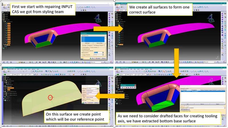
1. Creation of Dummy Tooling Axis
To create Tooling Axis first we have to create Dummy Tooling Axis.
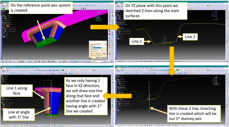
Note- Line we created with angle of 3deg primarily. If with 3deg draft analysis will found ok we will keep it, otherwise we will increase the angle so that all the surfaces will clear draft analysis.
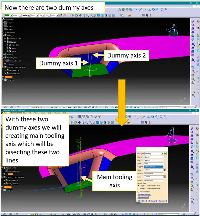
2. Creating main tooling axis
Creation of close surface using Class A, B & C surfaces-
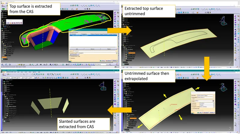
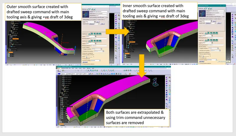
a. Creating Class B surface
Class B surface will be holding all engineering features like ribs, screw bosses, etc.
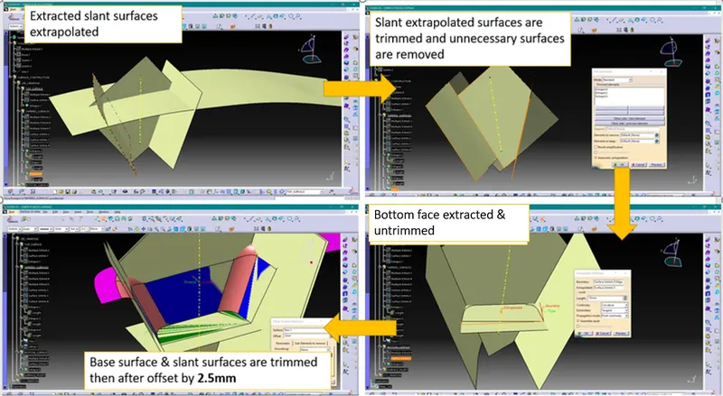
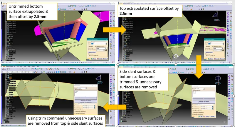
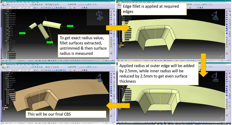
We need to create CBS(Class B surface) using CAS(Class A surface). The process of generating CBS is explained below-
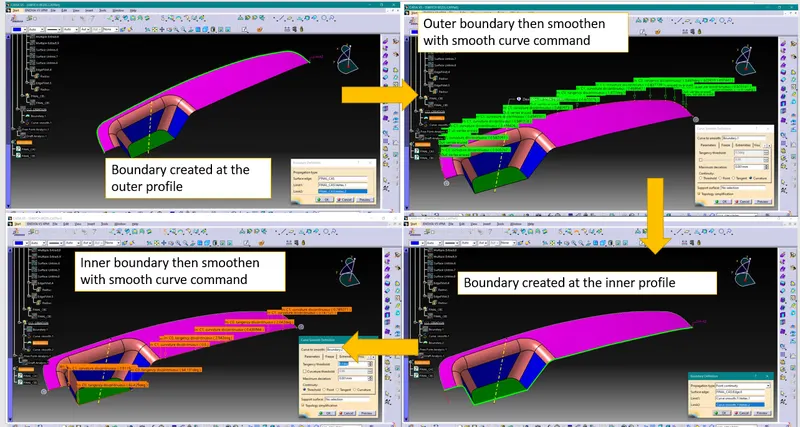
b. Creating Class C surface
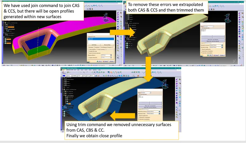
c. Creating close surface
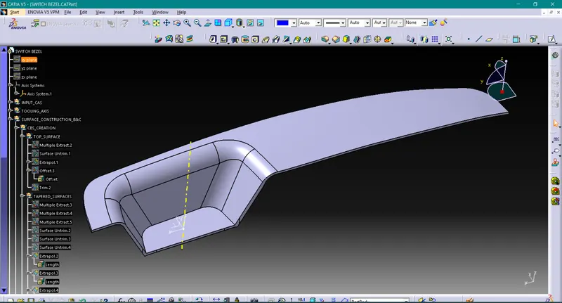
d. Creating solid surface from closed surface
Creating solid body requires completely closed surfaces or otherwise it will show error.
Using close surface command in part workbench we have created solid body
Draft Analysis-
Process of performing draft analysis in Catia V5-
1. Click on the draft analysis icon ( ) or go to Insert>Analysis>Feature Draft Analysis
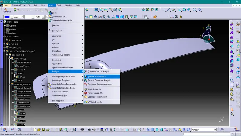
Note- While doing Draft analysis make sure you are enabling material view mode.
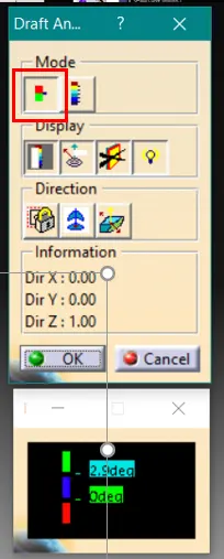
2. Switch on quick analysis mode by clicking on below highlighted icon
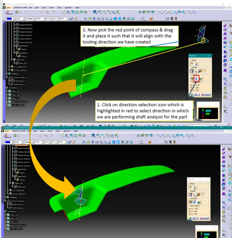
3. Selecting Draft Direction
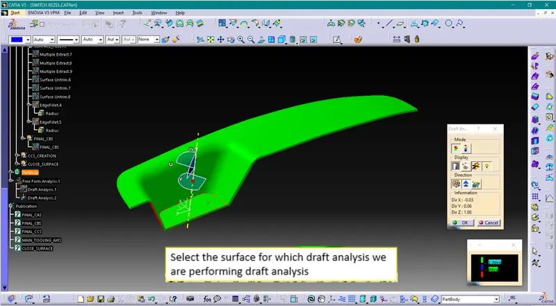
4. Selecting surface
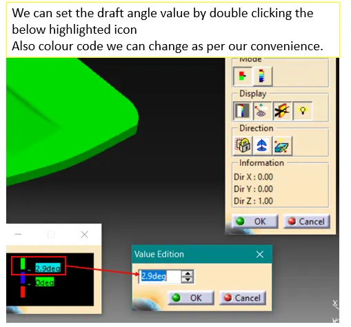
5. Input the draft angles
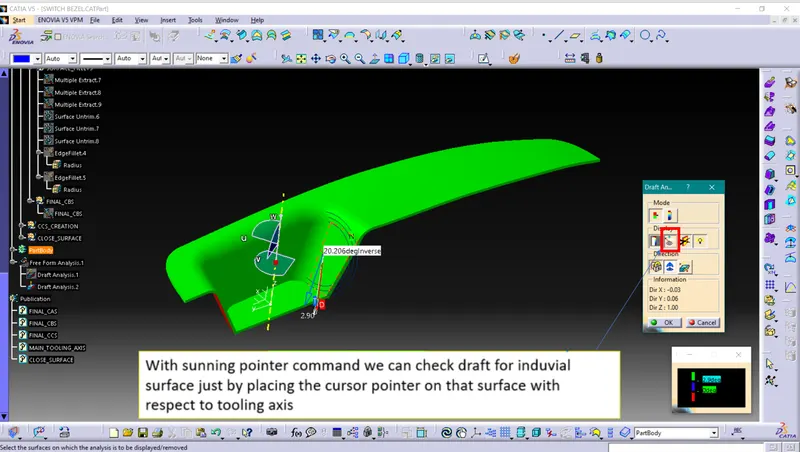
6. Running point
Draft analysis for CAS-
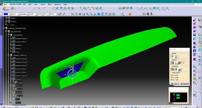
As we have discussed earlier regarding angle in creation 2nd dummy tooling direction, with 3deg inclination our surfaces are not clearing in draft analysis. So, we have increased inclination to 5deg.
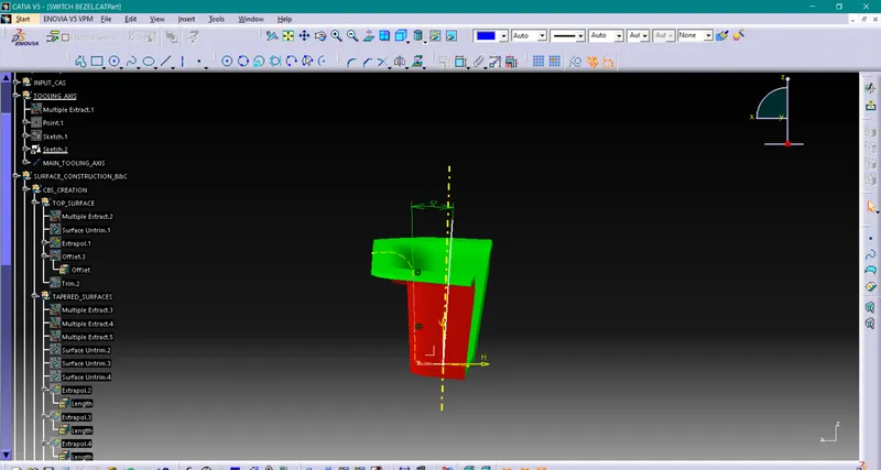
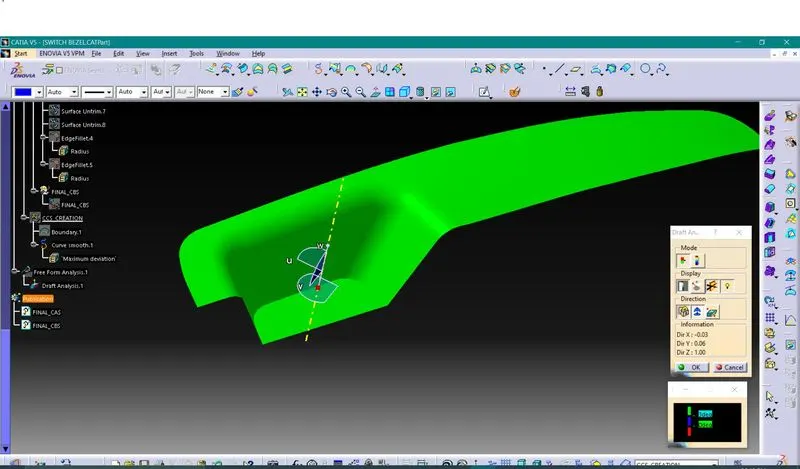
With 5deg inclination our drafted surfaces are clearing draft analysis
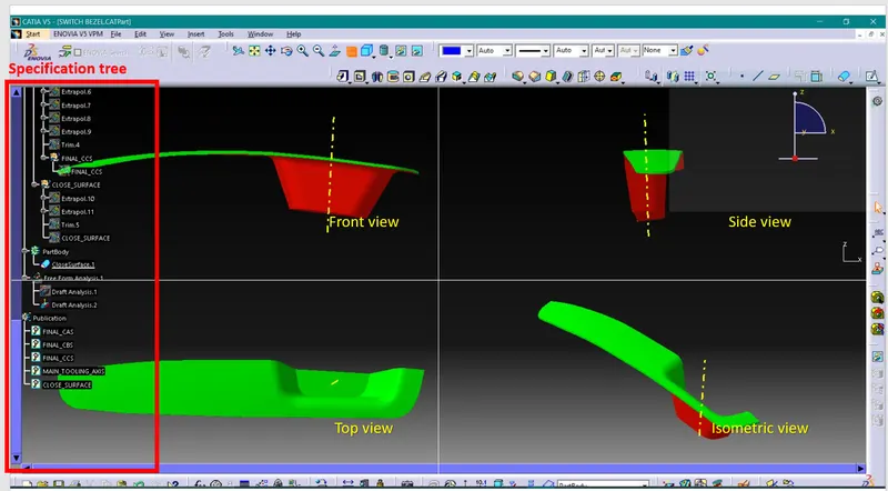
Draft analysis for Solid part-
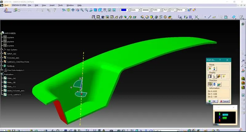
Solid model with the proper color code of the draft angle in various orientations (Isometric, Front, Side, and Top View)-
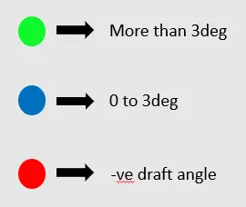
Screenshots of the solid model with the proper color code of the draft angle in various orientations-
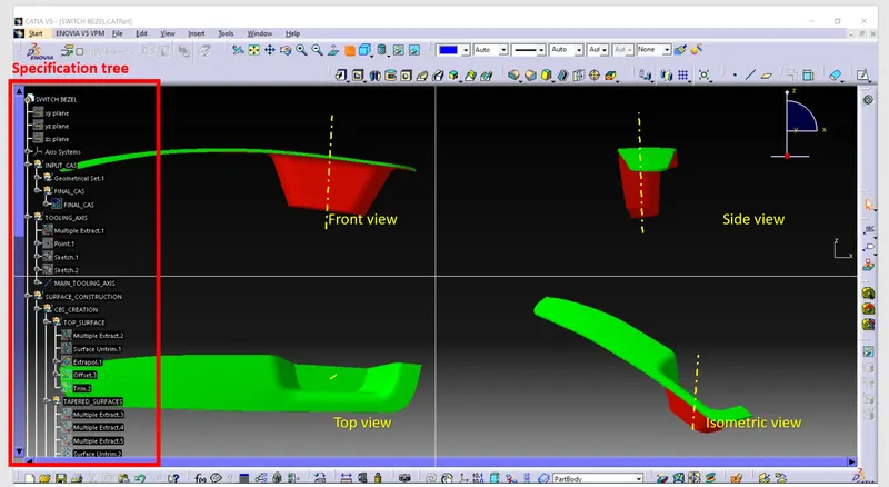
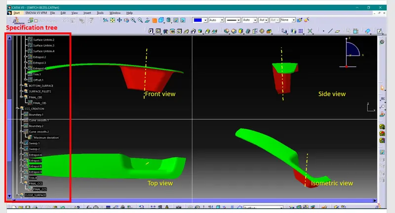
Conclusion-
1. We have understood how to generate class B & class C surfaces from input class A surface
2. We have understood importance of Tooling Axis
3. We have understood importance of Draft & Draft analysis
4. We have created solid body using closed surfaces.