Week 8 - Challenge 3 - Coin Holder Design
AIM:
To design a coin holder Plastic component through the given Class-A surface by creating a tooling axis and draft analysis of the given surface.
Take the Thickness of the component to be 2.5 mm.
DESIGN PROCEDURE:
- Using class-A surface create a tooling axis.
- Check draft angle.
- To create a base surface of model.
- To create a B-surface.
- To create a C-surface.
- To use close surface for creating a solid part model.
TOOLING AXIS:
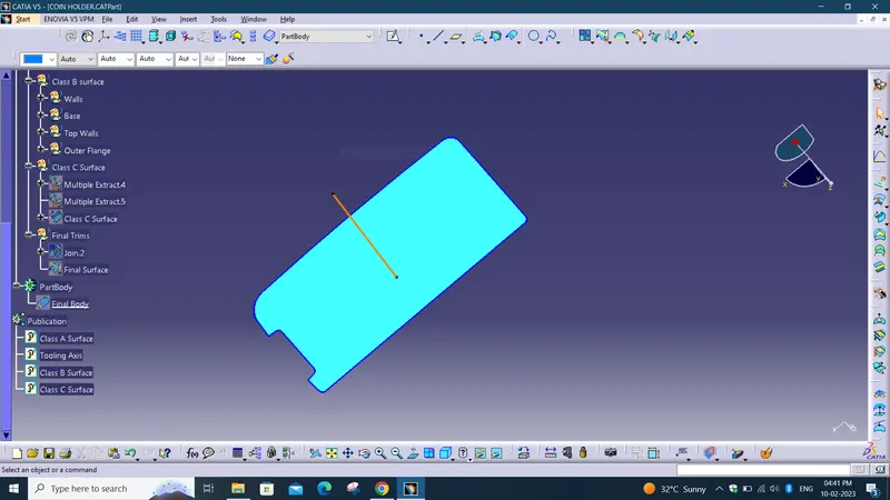
For this model, we use a line at mid-point of the base of the coin holder.
Due to perpendicular walls of the class A surface we use normal to surface method.
DRAFT ANALYSIS FOR CLASS A SURFACE:
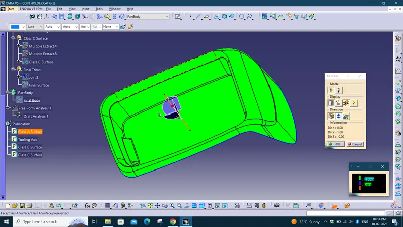
The Drafting analysis was performed on the class-A surface by using the Feature Draft Analysis command.
Using this command, the compass was set on the main tooling axis and the Draft angle was changed to 3 degrees.
CLASS A SURFACE
In automotive design, a class A surface is any of a set of free form surfaces of high efficiency and quality. It gives the aesthetic of the component which is created by the styling team and gives to the part design engineer to create the part with all engineering aspects.
We have been given the Class-A surface and the first thing to do is to make sure that the given surface has no gap in between them. We can check it visually and also with help of Join or boundary commands.
Class B Surface-
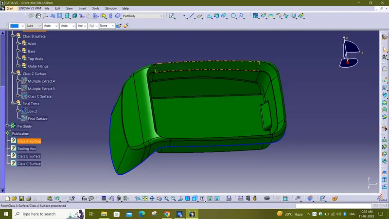
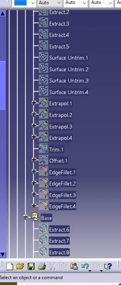
By extracting all surface seperatly, untrim thaem. After that offset all of them backward for 2.5MM to achive proper thickness. Then by extrapolatring thaem trim all the sutfaces accordingly to get proper shape. Make sure after final trimming there is no open edges.
FOR CLASS-C SURFACES
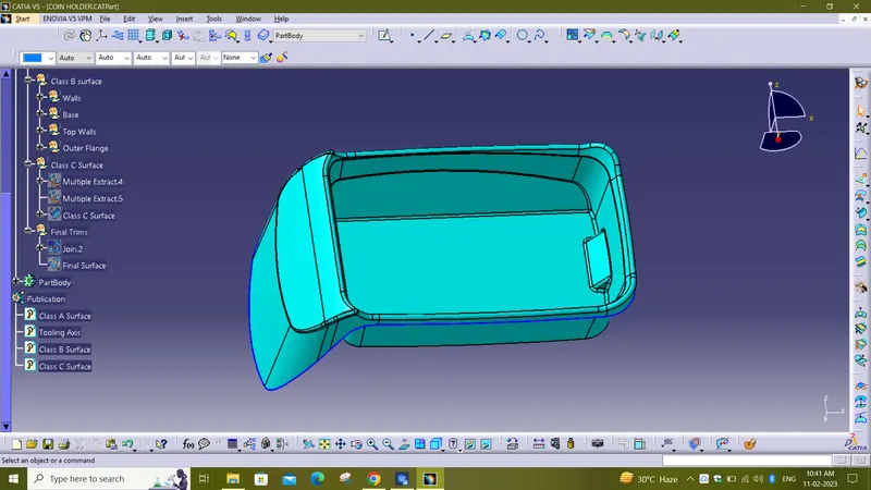
In this model, unlike the earlier models, we have used parallel tooling axis. Hence we cannot use ‘with draft direction’ option under sweep.
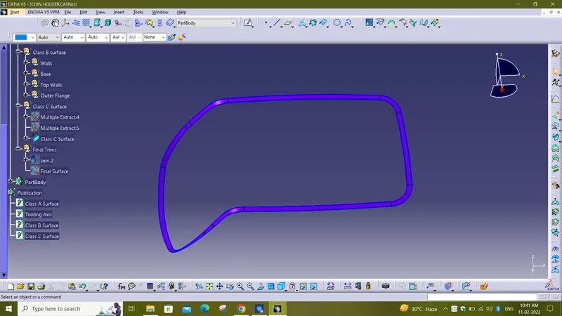
The C surfaces will mostly be created like shown below.
Here we will first get the boundary of the class-A surface and sweep it with reference surface option.
Similarly we will get the C surface for the hole to close it.
DRAFT ANALYSIS FOR A CLOSED BODY AND DIFFERENT VIEWS:
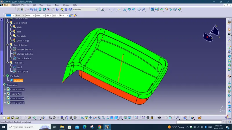
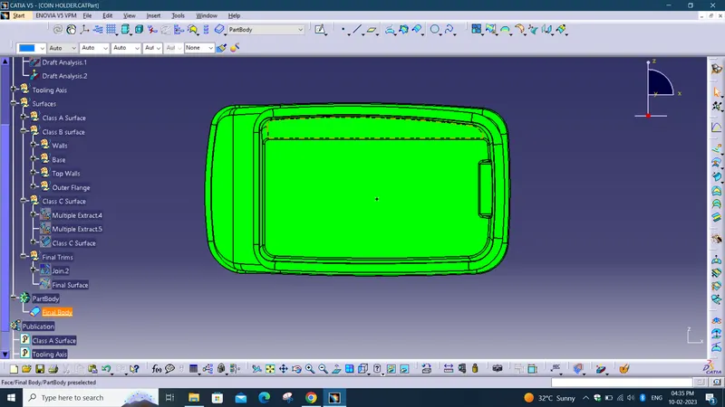
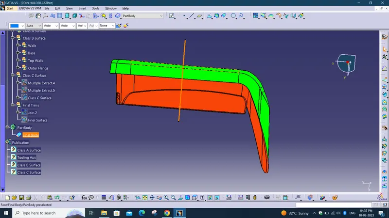
- To perform the draft analysis the view parameters are first set to Material mode.
- Then go to Insert >>analysis>>feature draft analysis.
- First, select the axis system and drag the axis system to align and coincide with the tooling axis and lock the orientation. This axis system defines the draft direction according to the tooling axis.
- Switch on the color scale and set the minimum draft value. Here it is set to 3 degrees and it will be displayed in green color. Any draft angle below 0 degrees will be shown in red color.
- Now select the running point tool to measure the draft angle at the various locations and then if all surface passes the draft analysis switch on the light effect that will show the component in green color if the component has the required draft angle.
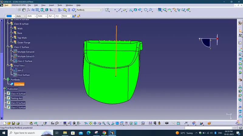
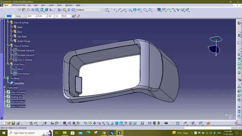
FOR FINAL MODEL
Join class-A and class-C surfaces together.
Then join class-B surface to them.
Go to the part design and close the feature.
Run draft analysis on the model.
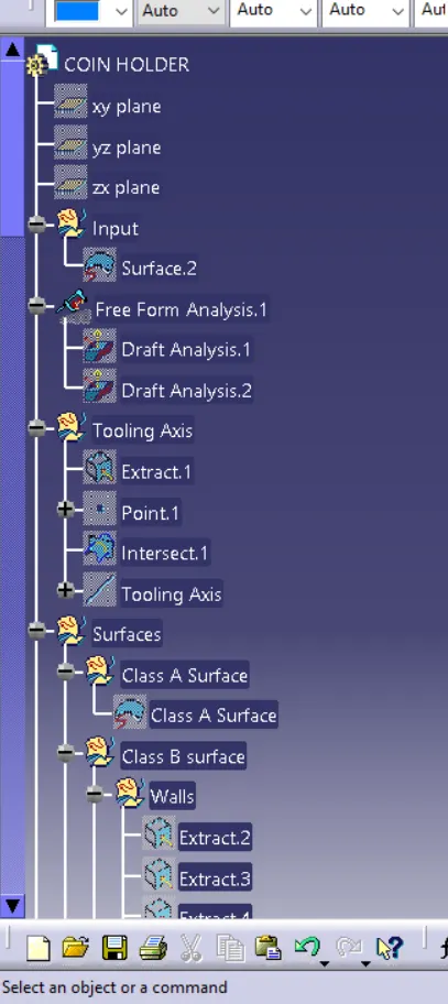
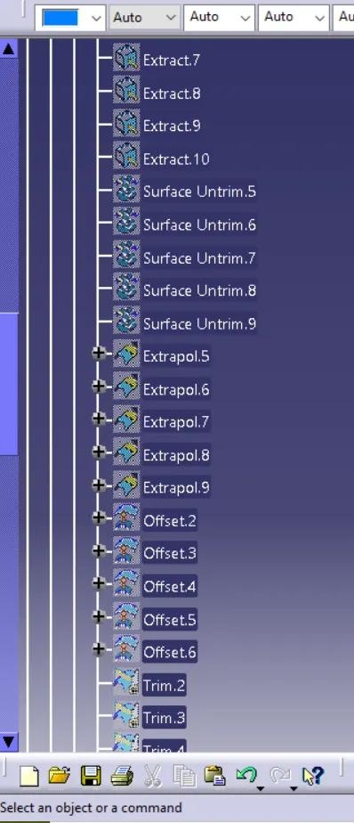
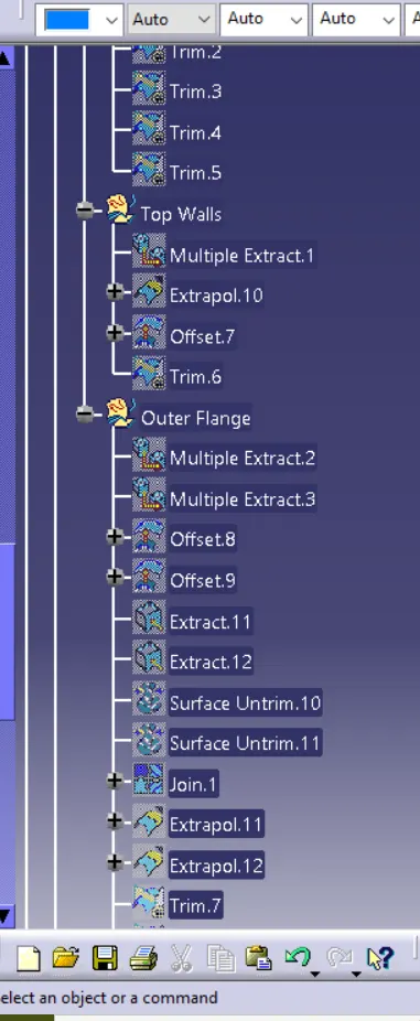
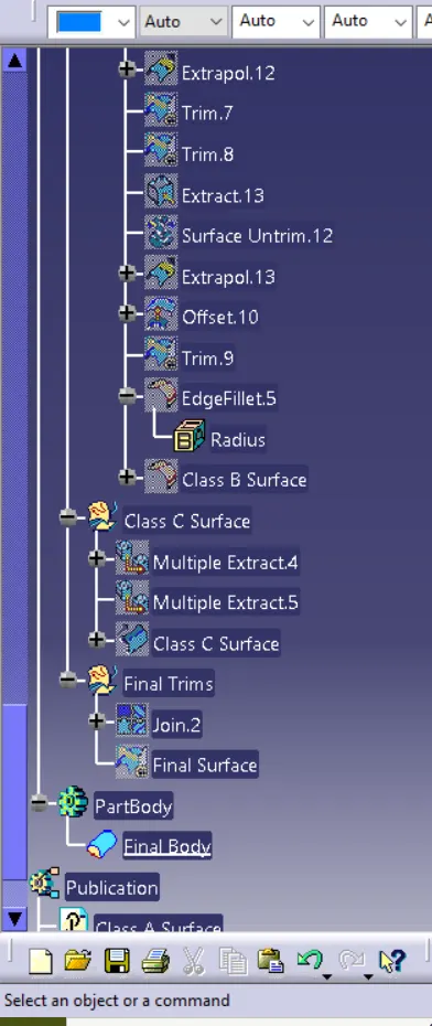
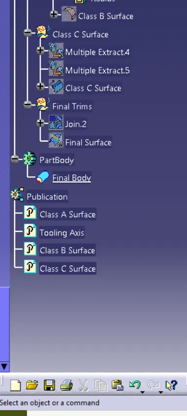
TREE STRUCTURE:
CONCLUSION
- Created the Coin Holder component using the given Class-A surface.
- the tooling axis for the given Class-A Surface is created which meeting the requirements of the draft angle
- Draft analysis is done on the CLASS A surface
- Draft analysis is done on the model.
- Using the Close Surface feature solid body is created from the surface
- Publications: Tooling Axis Class A, B, and C surface and closed surface