Week 8 - Challenge 3 - Coin Holder Design
Coin Holder Design
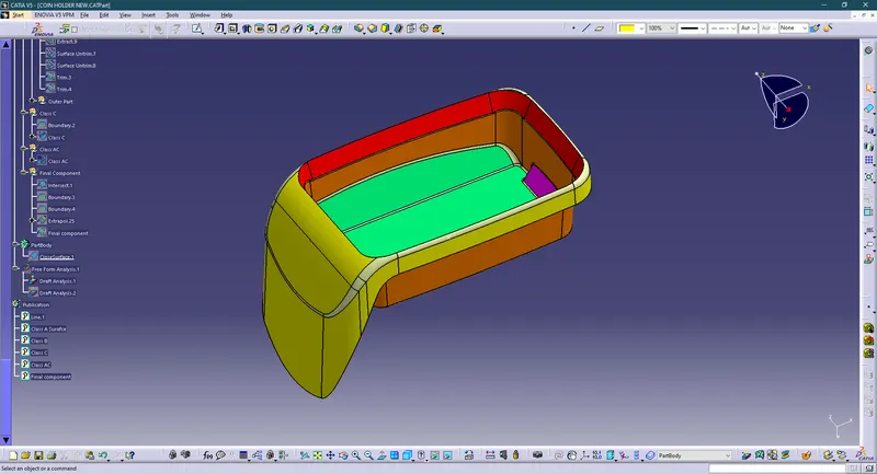
Aim: Create the Coin Holder Plastic component through the given Class-A surface. To begin with, the tooling axis for the given Class-A Surface should be created meeting the draft angle requirements and performing the draft analysis on the model at the end.
The thickness of the component is 2.5 mm
Class-A Surface:
Introduction:
CLASS-A SURFACE: a surface made by the designer which is given as an input to the plastic modeler to work on. It is an aesthetic surface and the outermost surface.
CLASS-B SURFACE: a surface below a certain thickness from the class-A surface is a class-B surface. This is the surface that contains engineering aspects of a model.
CLASS-C SURFACE: a surface that joins class-A and class-B surfaces is a class-C surface.
Tooling axis: the direction in which the mold opens or the core cavity opens. By providing a tooling axis to the component we can perform the draft analysis of the component.
Design procedure:
- Checking Class A input for imperfections.
- Ensure that the class A surface has no gaps and no discontinuities of the surfaces using the boundary command.
Draft Analysis :
The Draft angle is the amount of taper for molded or cast parts perpendicular to the parting line. It can be measured in degrees. A functional part for injection molding has to have drafts facing both cavity and core sides to reduce the risk of damage to the parts and ensure ejection. And also important is to overcome the vacuum forces by letting air in between the metal and the plastic for the part to release properly. Adding maintaining a decent cosmetic finish.
The draft should be a part of the design for manufacturing and the plastic products Designer should be aware of its need at the outset of the design process. This allows considerations for design requirements to be taken into account.
Design Consideration
- Class – A surface should be aesthetically smooth and good.
- Class – B surface should have all the supporting features like ribs.
- The parting Line should coincide with the B surface since flashing couldn’t affect the aesthetic of Class – A.
- Class – C surface should also pass the draft analysis
Nominal values for Draft angle :
- 3 Degrees is the nominal Draft angle.
- 7 Degrees for a textured surface.
- A minimum of 0.5 Degrees can be manufactured with special tools. But it will increase the manufacturing cost
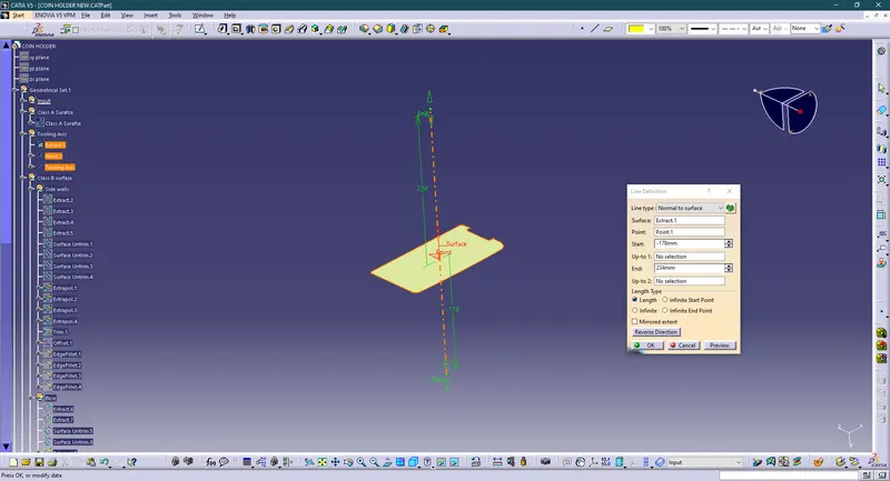
Tooling Axis Creation: Generally tooling axis is created using bisecting line method. But in the components where it has a bin, then the tooling axis is considered as a line normal to the base surface of the bin. The same is done with this component. A line normal to the base surface is created and considered as a tooling axis.
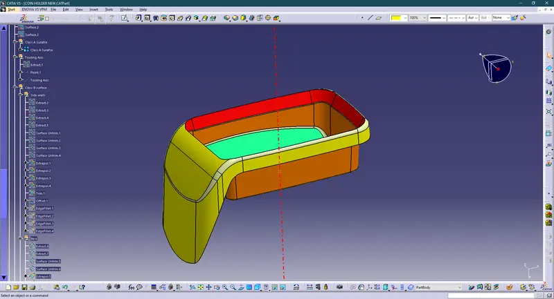
Draft analysis of Class- A
After creating a tooling axis we do the draft analysis. Before drafting we have to make sure that in the view mode it is selected for the materials.
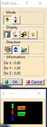
After selecting the feature draft analysis tool we drag the compass from its position to the tool axis. Then lock the compass. After that select anywhere on the component and it will give you the result.
We change the minimum draft for the component to 3°.
We can use the running point option to check the angle of the component.
We can even modify the color according to our preference.
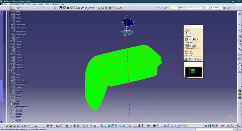
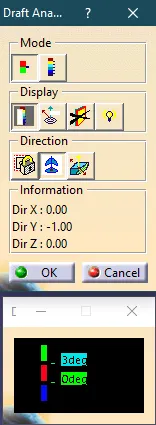
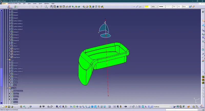
The above image gives us a clear picture of the draft angle associated with the Class-A surface, It is clear that the surface has a draft of more than 3 degrees that can be easily seen in the color scale window that shows green color means having an angle more than 3 degrees
CREATION OF CLASS-B SURFACES
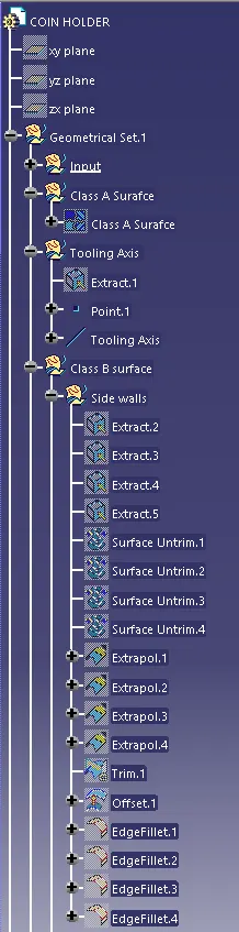
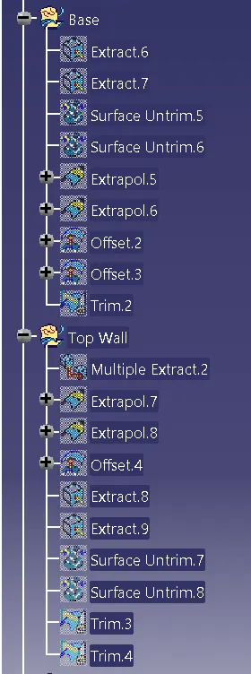
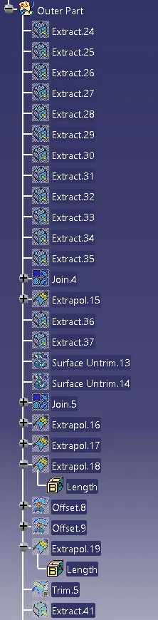
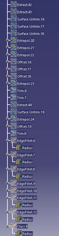
We have divided the entire model into the base, side walls, inside side walls, and outer flange and worked on them one by one.class B surface is created using the standard procedure by extracting, un trim, extrapolating, and offset commands. B surfaces of all these subparts are created and trimmed together to join as a single surface.
The offset distance is kept at 2.5mm
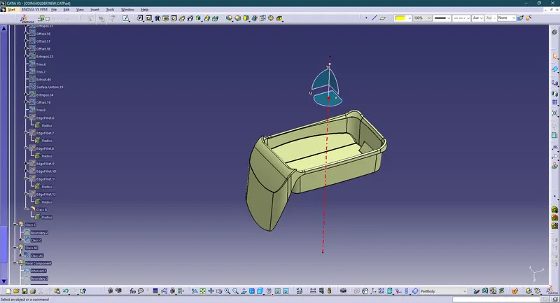
CREATION OF CLASS C SURFACE
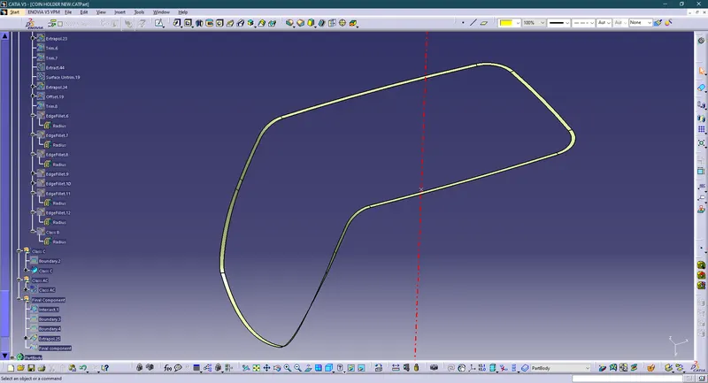
We first extract the edges from the Class A surface with the help of the boundary command which we create the path for a sweep for class C and we even extract the adjacent surfaces to use them as a reference plane. select the sweep tool and in that we select with reference draft direction and then we change the angle to 90° for it to be horizontal.
Joining class-A surface and class-C surfaces together.
Then trim class-B surface to them this will make sure that we get a closed surface. We can check it using the boundary tool, if it gives an error that means that the component is closed.
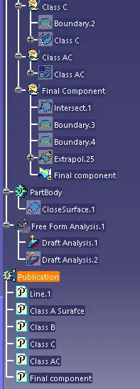
Tree Structure
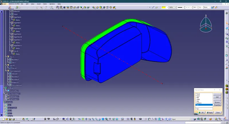
Isometric
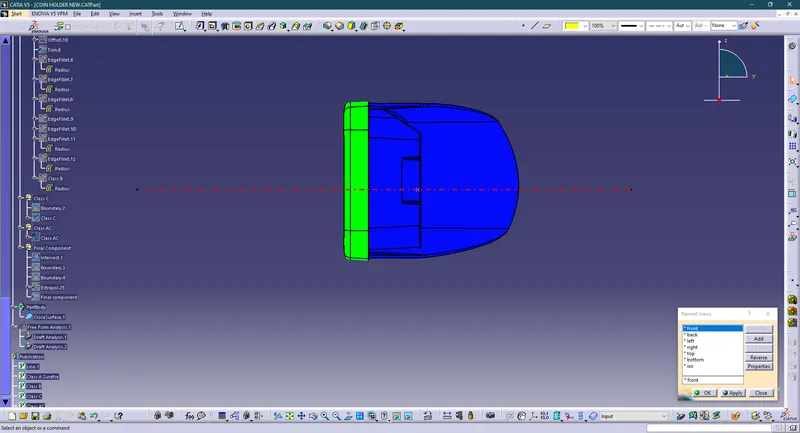
Front
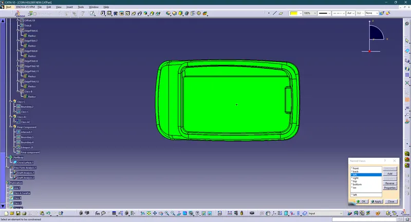
Left
Right
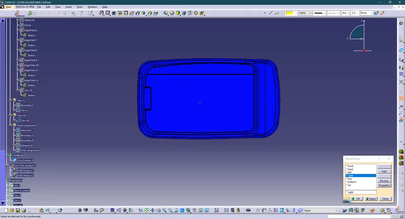
Top
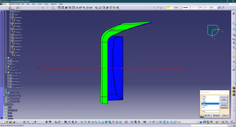
Bottom
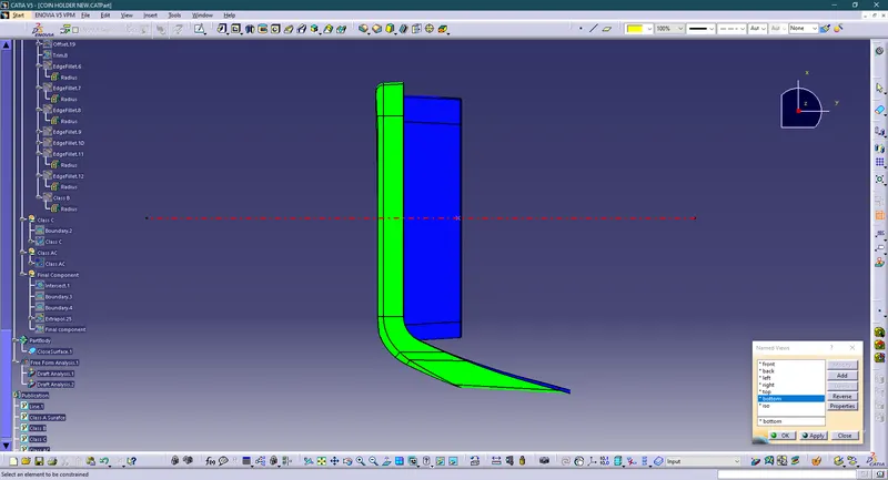
Procedure for performing Draft Analysis:
- Go to the Insert menu and select the Analysis option.
- Select Feature Draft Analysis.
- Select the Material option and select the surface.
- Drag the compass and place it on the tooling axis.
- Make sure that the top surface is in green color as the draft angle should not exceed 3deg.
- Click on Okay.
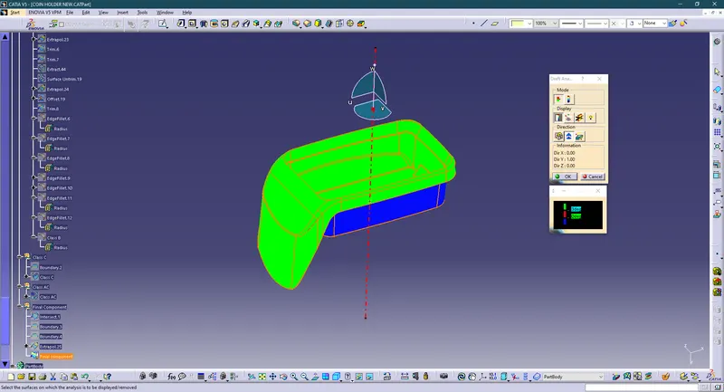
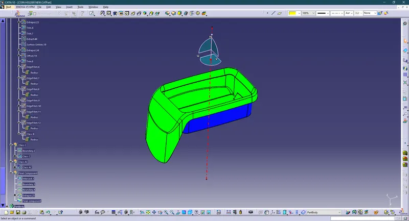
Here we can see that the Class A surface is Green. Class B and Class C are Blue. We can see that Class C is Blue because we have given the Sweep of 90 Deg. And Class A is green from which we can say that the component we have manufactured can be ejected unharmed.
Conclusion :
Hence the Coin Holder Challenge component through the given class A surface and created the required Tooling axis and performed the Draft analysis on the model and also for the solid model. so this Draft analysis feature is very useful to check the Draft angle and can check whether this part makes any problem while manufacturing that product. And the nominal Drafting angle is 3 Degree so we need to design the part with a minimum of 3 Degree has the Draft.