Week 8 - Challenge 3 - Coin Holder Design
Week 8 - Challenge 3 - Coin Holder Design
AIM :
Create the Coin Holder Plastic component through the given Class-A surface. To begin with, the tooling
axis for the given Class-A Surface should be created meeting the requirements of the draft angle and at the
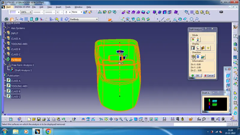
end perform the Draft analysis on the model.
Take the Thickness of the component to be 2.5 mm
CLASS A SURFACE :
Class-A (or 'Strak') is a term used in specifically in automotive design. It describes the final production
Class data for the aesthetic parts of the car. The term 'Class A' is often misunderstood, but it's generally
seen as the 'Holy Grail' of Class modeling.
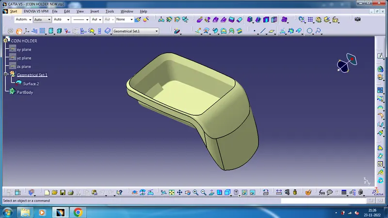
CLASS A ( Given File )
TOOLING AXIS :
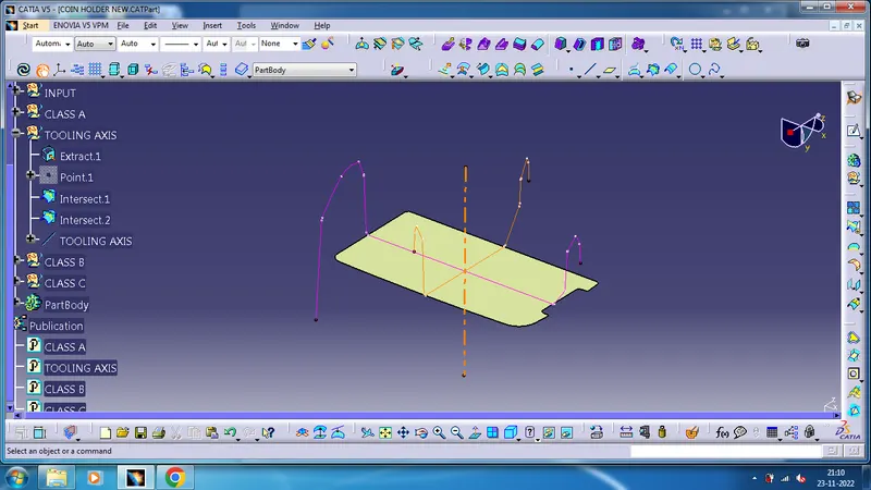
- Now we create tooling axis for the Class A. First a create axis system for where we want, then we create intersect based on the axis system.
- Extract the bottom surface and insert point on a surface then create lind based on a point.
CLASS A DRAFTING:
CLASS B :
SIDE WALL:
- Now create a class B surface.
- In class B, first create base of class B from class A. Insert geometrical set define as class B, that is base of class B.
- Use extract command and extract a base from class A. Then use untrim tool get full body of a base. Next use extrapolate tool extended a base , then offset of 2.5 mm.
BASE:
- Insert a new geomentry set for wall define as classB surface.
- Since use extract tool, extract from classA surface and use untrim tools, untrim for a extract body we get untrim body and extrapolate for a untrim body we get a proper shape of the sheet.
- Then trim ribs to get the proper wall shape and offset of the trim. That offset set is a final ribs .
TOP WALL:
- Now extract a top wall from class A, then use extropolte the extract body. Then trim the body.
PROJECTION WALL:
- Extract a required part from class A, then undrim a extract part. Next extrpolte some distance. Then trim a part, then offset. Now trim with base then get final part of a inside, join with remain parts.
INITIAL TRIM AND FILLETS:
- Unhide bottom surface and trim the one by one with base then get the proper class B.
- Then use fillet command, fillet tha corner edges then we get a final Class B surface .
CLASS C :
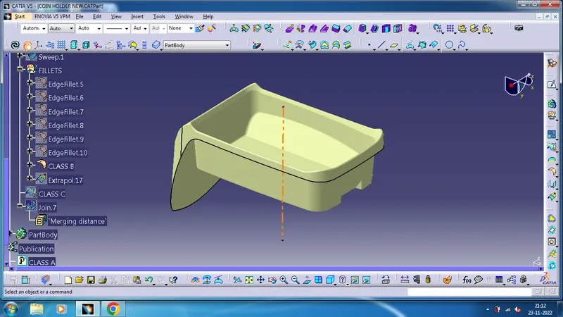
- Class C is nothing but its connecting part of Class A & B.
- Unhide the class A and take boundary of its and now boundary select the all corner of a class A and use sweep commends the we get a class c of boundary in Class A.
- Then trim it finally get class C.
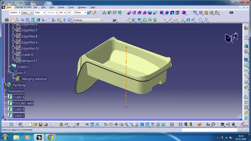
TREE STRUCTURE:
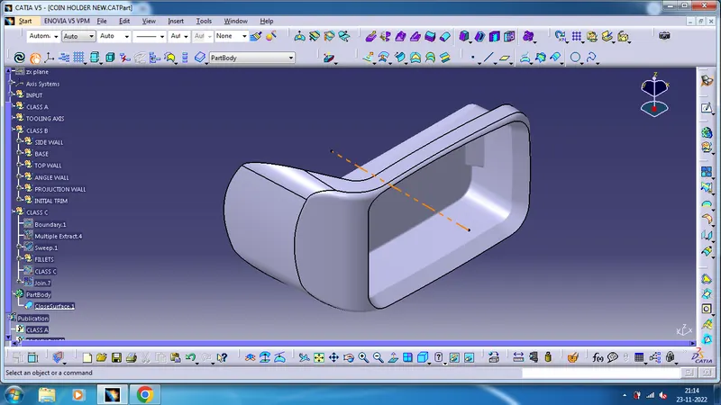
ISO METRIC/CLOSED VIEW
CLOSE BODY :
- Go to the part body workbench then use close boby tool and finally get close body of base bracket
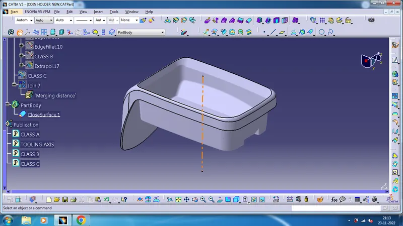
FRONT VIEW:
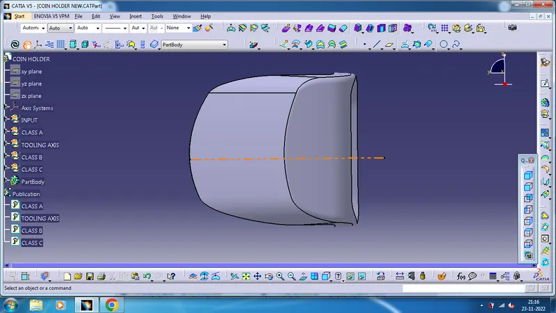
SIDE VIEW:
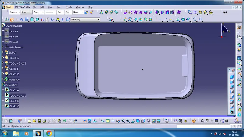
TOP VIEW:
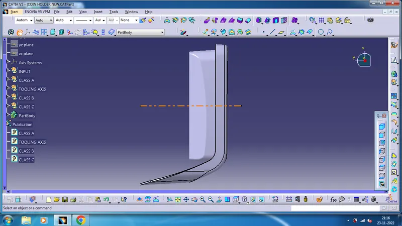
FINAL DRAFTING VIEW:
RESULTS :
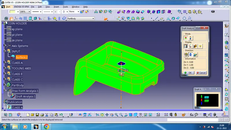
Finally used draft analysis tool, analysis model get positive results from a draft successfully Class A,B &
C is required angles from a draft angle analysis. Analysis the draft angle red is below 0 degree and green is 3
dgeree, blue is between tha 0 and 3 degree.