Week 8 - Challenge 3 - Coin Holder Design
Draft angle
- Draft analysis helps to detect if your drafted part is easily removable from the mold
- All plastic components will have a minimum draft of 0.5 to 3 deg.
- If a mold wall is perpendicular to the part ejection ,there will be ample friction or interference between the mold and the part which will not allow one to release from the other
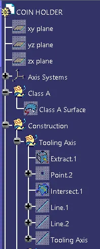
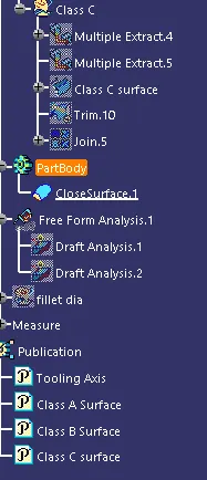
Tooling Axis
- The tooling axis is a direction along which the core and cavity tends to move.
- Here the tooling axis is created in direction, which is normal to one of the Flat surface of the Coin Holder
Creating tooling axis
- Open the given CAT part file.
- check for gaps between surfaces for that click on join and then preview
- find the correct tooling axis where the material don’t interfere with the tooling axis and all the elements can be created
- create an axis system using the surface at the bottom and use point to create the axis system
- Intersect the yz plane with respect to the class a surface walls.
- Hide the class A surface and create point to point lines on the suspected drafts
- Create a bisecting line with the two lines and point to create a tooling axis
- The tooling axis is created for the component
Isometric View
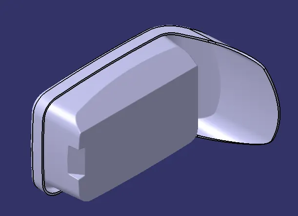
Front View
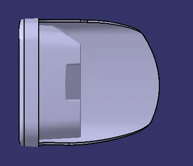
Side View
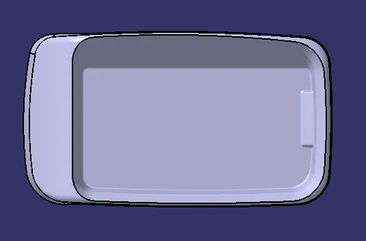
Top View
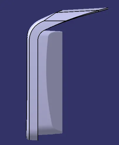
Draft analysis
Report for the CLASS A surface:FOR 3deg Draft it is ok.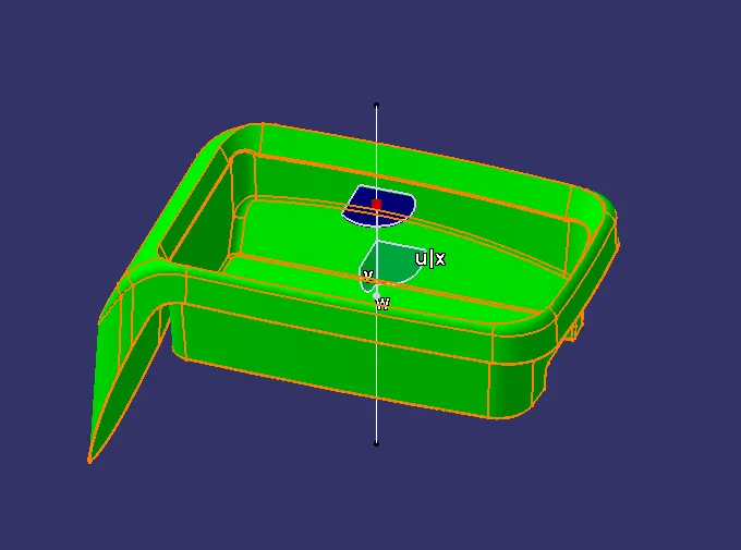
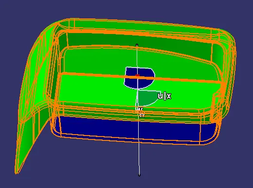
Report for the final plastic component
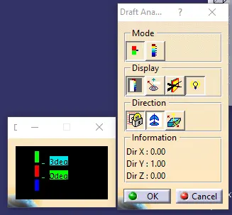
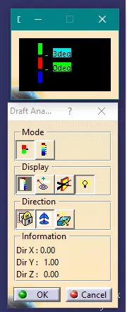
Dialog box