Week 8 - Challenge 3 - Coin Holder Design
COIN HOLDER
To Create a coin holder plastic component by closed method with reference to the Class A surface and do the draft analysis of the component.
STEPS
- The Class A surface is checked for the connectivity of the surface and ensure it is completely joined and there will be no gap between surfaces.
- If it is not joined together make it with a minimum tolerance of 0.001 to 0.003 and check for connectivity of the surface.
- Connectivity of the surface can be done by two ways by join method and by boundary method
- Split the surfaces into multiple profiles than identify the surface where it is not possible to create a tooling axis andd check on which direction is best fit for tooling axis and then defined the tooling axis and draft direction.
- Here for defining the tooling axis first we have created a point at middle of the base surface and create an axis with respect to that point than define the tooling axis using the intersect method by creating a bisecting line.
- After that do a draft analysis on the class A surface and identify the draft angle then give the nominal value for the draft.
TOOLING AXIS
- The direction in which the mould open and closes is called the tooling axis direction.
- Check the connectivity of the surface and ensure there will be no gap between the surfaces and then define the tooling axis.
- While creating a tooling axis always ensure to give the tooling axis on a flat length surface or the surface which have a hole on it.
- Create a point on the middle of the face surface by using point on the surface command then create a intersection for the surface and extract the reference lines which will be helpful for creating the dummy tooling axis using the intersect method by creating a bisecting line.
- Use the line command and draw the lines which is aligned with the extracted lines and extanded it to the required length.
DRAFT ANALYSIS
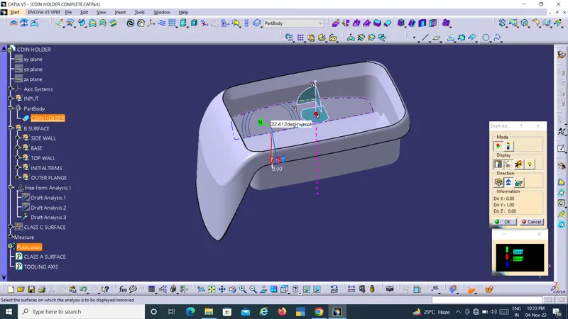
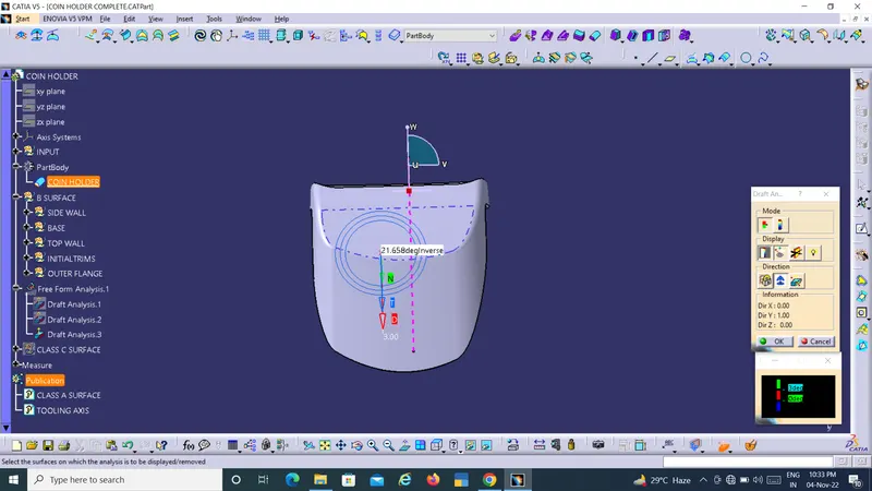
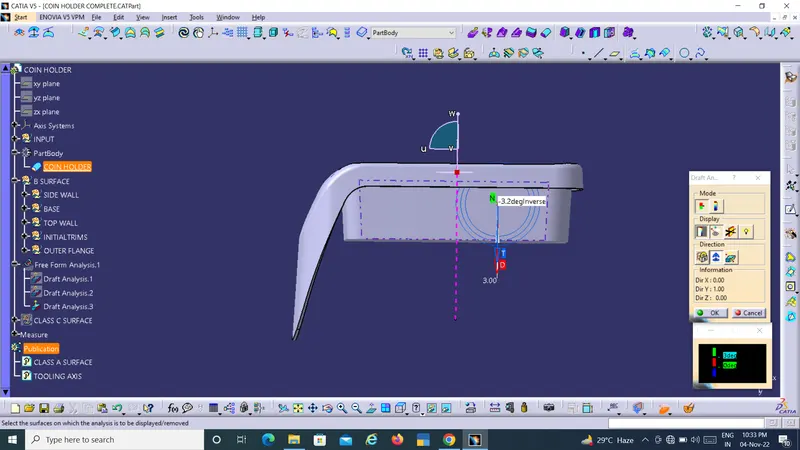
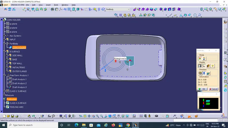
- Draft allows for the component to release from the mould, most parts or application require a minimum of 0.5 to 1 degree draft angle and 3 degree draft angle is widely used as per the norm.
- Change the Material mode to customize mode before moving to the draft analysis.
- Insert-analysis-feature- draft analysis.
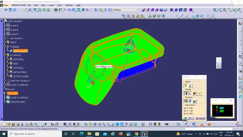
- Defining the Draft direction select draft analysis from Tool Bar and click on the comapass symbol and pull the compass from the right side top corner of the workbench and place it on the component where want to do the draft analysis. 'W' of the compass and tooling axis should be align on the same line.
- Once the comapass is aligned with the tooling axis click on the lock symbol and drag on the surface we will get a Cross Mark than select that point a table will appear it shows the draft value on the table we can adjust the draft value and analysis it for all the edges and surfaces.
- By clicking on the Surface and using the Flipping tool we can assign the flipping direction, the color of the surface change as per the flipping direction.
- analysis under running point and move the mouse on the surface and it will show the detail of the surface deg. direct at each and every point of the surface.
B SURFACE
- B Surface can be divided into four surfaces The side walls, top walls, outer flange and the base surafce and later trim them altogether.
- first step is to create the side wall surfaces by extracting the required surface from class A and untrimmed it thus we will get a single surface which will be extrapolated to get the required size and finally offset it to the inner side of Class A as per the thickness of the material and trim them together and apply the required fillet by measuring the value from class A.
- Base surface of the component is then extract, untrimmed, extrapolated, offset and trimmed
- The top walls can be directly extrapolated from the extracted surface and offset it for the required size of the material.
- then join the base, side wall and top wall by trim operations.
- As the outer flange is surface complex it can be divided into two parts and extract them then go for extrapolation, offset, split and join operation and finally check for connectivity by intersecting method.
- Now all the four geometries are trimmed together to get the B surface
- Fillet is applied to the required surface by measuring the fillet value from the Class A surface.
C SURFACE
- C Surface has been created from the Boundary lines of Class A surface and By extracting the Supporting Surfaces than Sweep the boundary lines with reference to the extracted surfaces.
DRAFT ANALYSIS ON CLASS A SURFACE
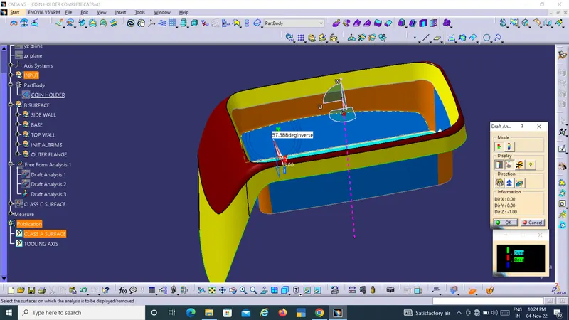
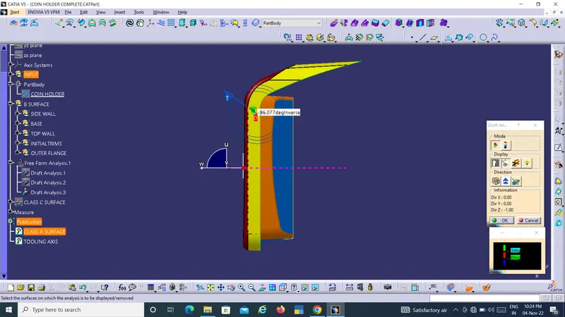
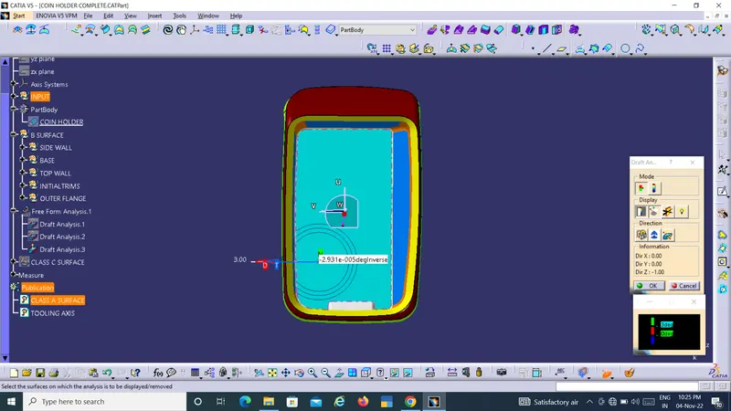
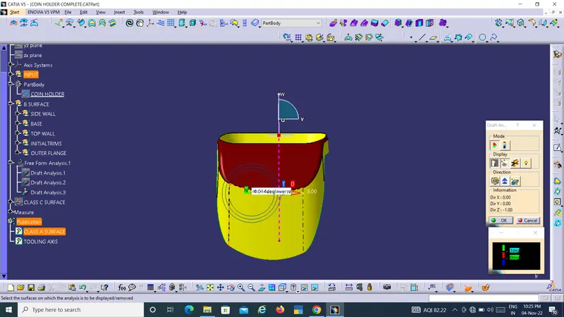
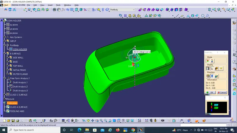
DRAFT ANALYSIS ON SOLID BODY