Week 8 - Challenge 3 - Coin Holder Design
Week 8 - Challenge 3 - Coin Holder Design
Aim -
Create the Coin Holder Plastic component through the given Class-A surface. To begin with, the tooling axis for the given Class-A Surface should be created meeting the requirements of the draft angle and at the end perform the Draft analysis on the model.
ABOUT SURFACE AND DRAFT ANALYSIS
Class A surface: Class-A surface is a term used in most automotive designs to describe a set of freedom surfaces of high efficiency and quality.
Class B surface: Class B surfaces are the secondary surfaces that you can we see sometimes but are less important.
Class C surface: Class C surfaces are the surfaces that connect the class A and Class B surfaces.
Draft analysis: Draft analysis is performed on components where the ejection of materials happens after the material is made inside the tools.
Creation Of Tooling Axis:
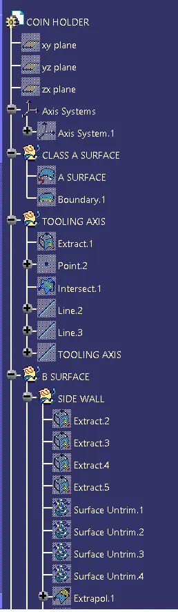
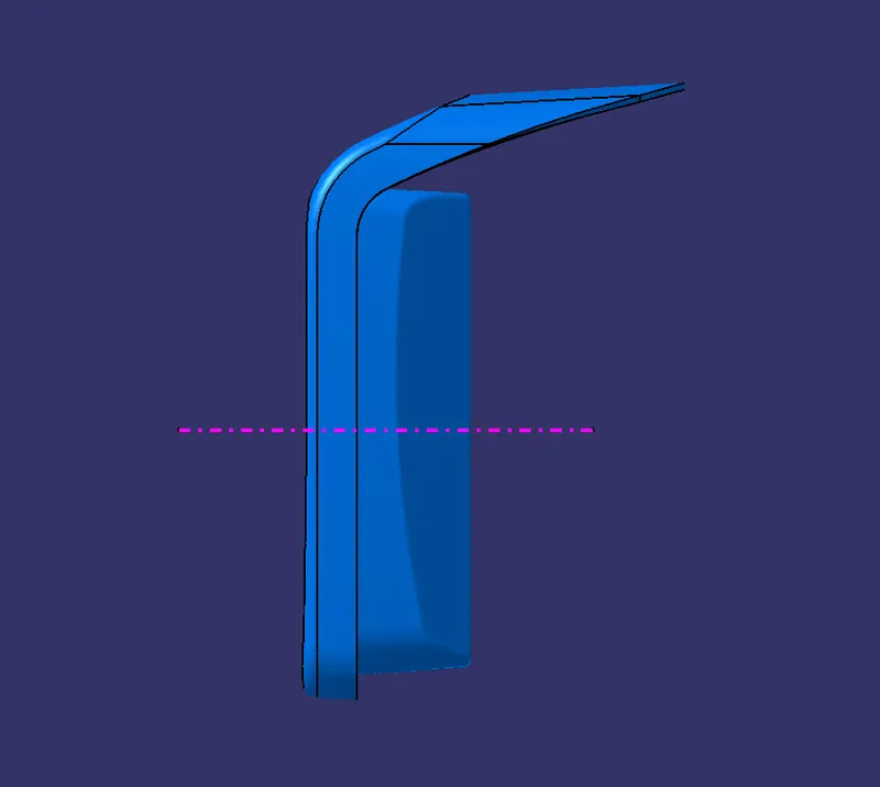
- To continue the designing process we need to create the tooling axis first for the surface.
- For that first extract the base suface and create a point and an axis system in on that point.
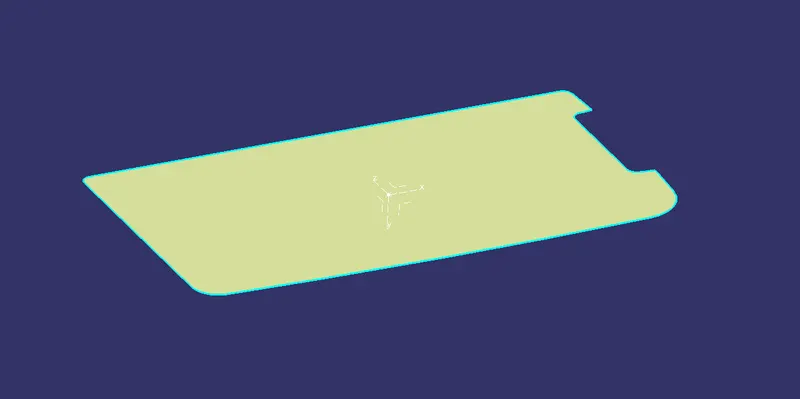
- Then Intersect the A model with the plane perpendicular or to the axis system.
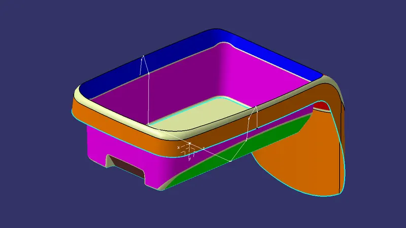
- Again intersect the model with another plane and extend the lines perpendicular to it.
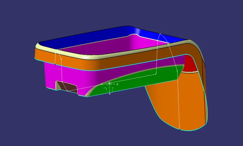
- Create a bisecting line by bisecting option in Line definition.
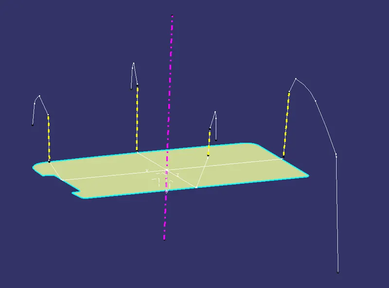
- Here the Pink dotted Line is the tooling axis.
CREATION OF B SURFACE :-
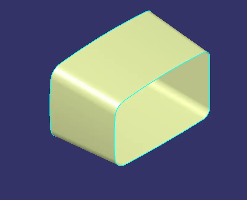
SIDE WALL
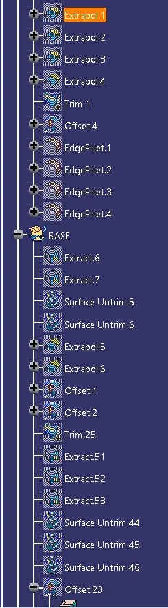
BASE
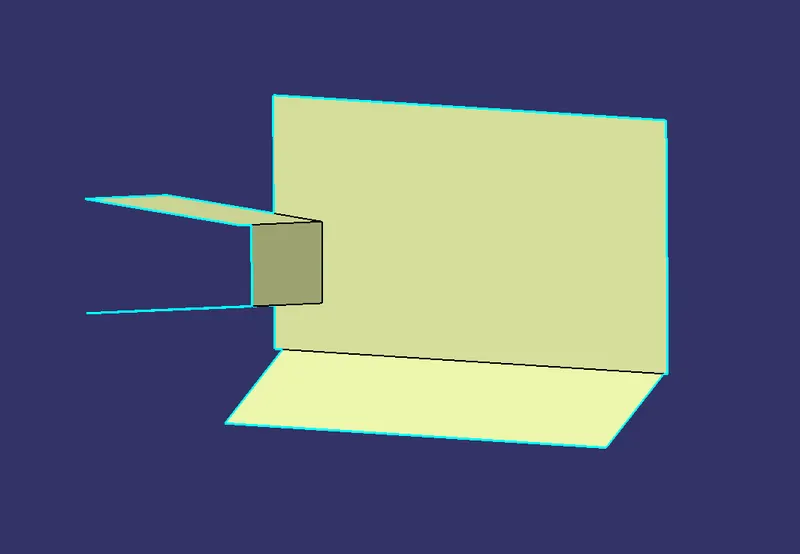
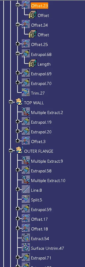
TOP WALL
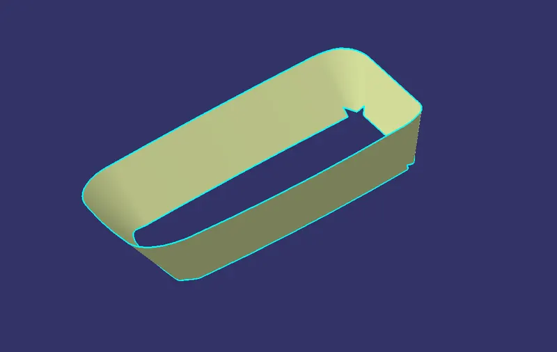
OUTER FLANGE
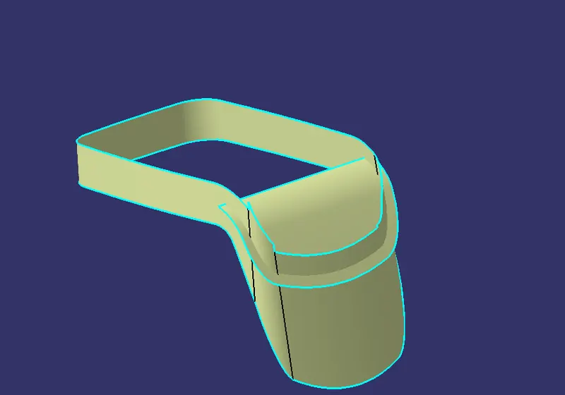
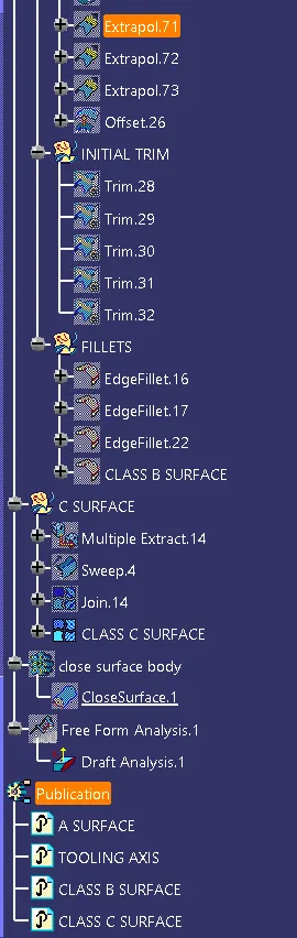
TRIMS
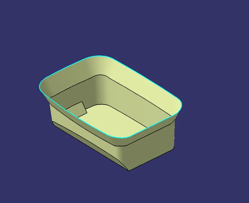
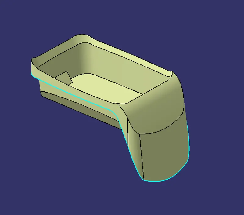
FILLETS
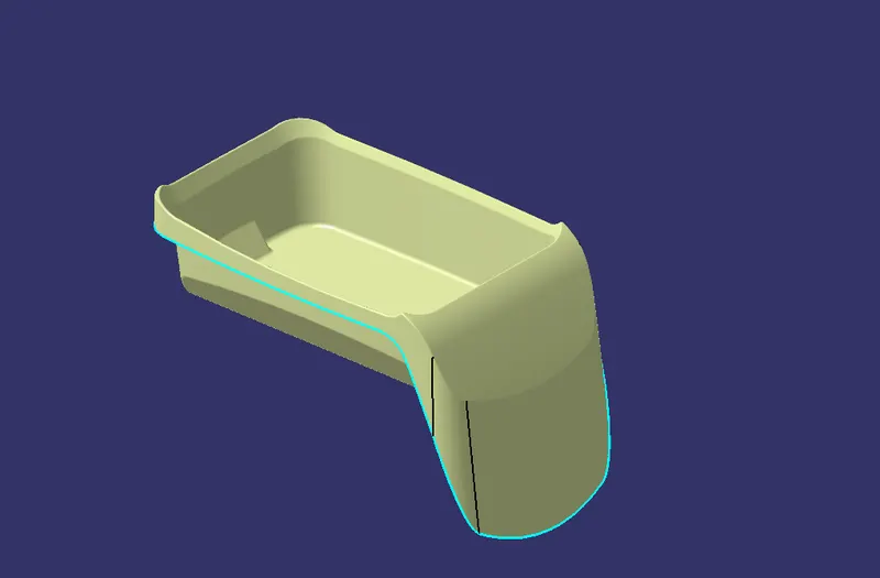
CLASS B SURFACE CREATION:
As usual B surface is created using the standard procedure by extract, un trim, extrapolate and offset commands. B surface of this coin holder is divided into a base, side walls, top wall, and outer surface. B surfaces of all these sub-parts are created and trimmed together to join as a single surface.
The offset distance is kept at 2.5mm as the component thickness is 2.5mm.
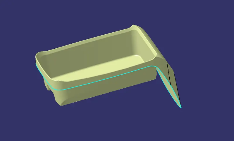
CLASS C SURFACE CREATION:
Class C surface for this component is created using sweep command. All the ends of component surface was facing downwards, so the C surface will created perpendicular to B surface.
To create C surface boundary of Class A surface and surfaces adjacent to boundary are extracted. Then sweep with reference surface commands is used and surface is created at 90 degrees.
EXTRACTED A SURFACE BOUNDARY
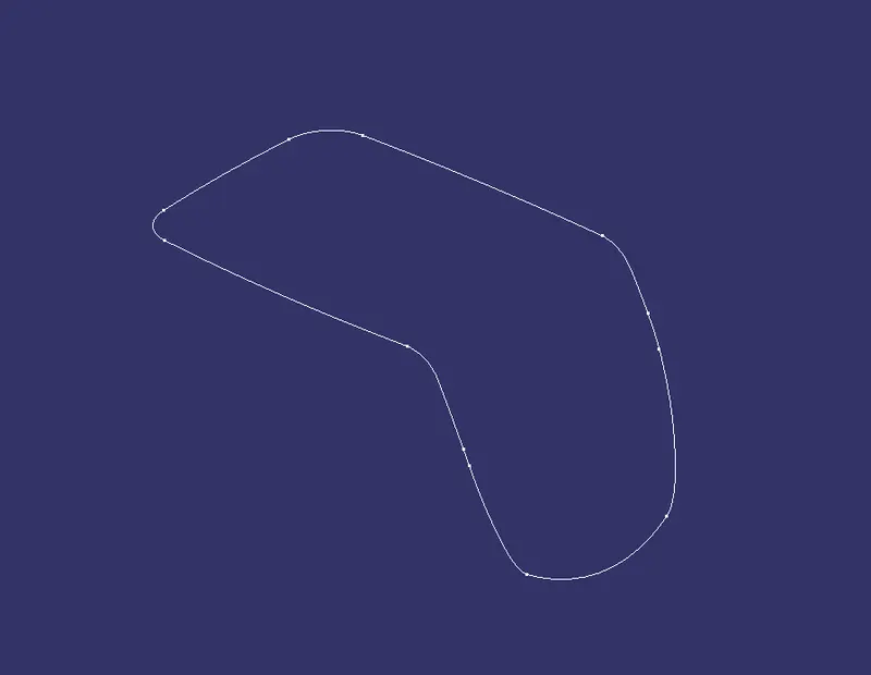
SWEEP COMMAND

DRAFT ANALYSIS : -
The draft analysis technique is used to analyze whether our part model created in CAD is manufacturable based on the draft condition applied. Here the part should get easily removed from the panel dies (in case of Sheet metal part) or Mold (in case of plastic).
Draft analysis is performed on Class A to check the validity of the tooling axis. During draft analysis, it was observed that bin walls are having a 90-degree angle with the base. There is no minimum draft given to the walls. Since we are not authorized to make changes to the Class A surface, we can inform the Class A designer to give the minimum draft to the walls.
- Draft analysis is done using featured draft analysis tool
- Use the compass fucnction to aling the compass to the tooling direction and lock the direction using lock function in the draft analysis tool bar.
DRAFT ANALYSIS OF CLASS A SURFACE
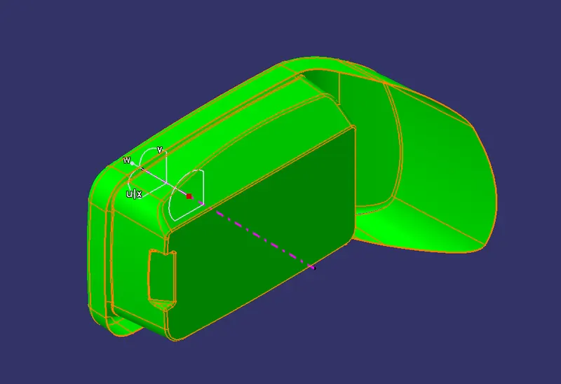
DRAFT ANALYSIS FOR FINAL COMPONENT
FRONT VIEW OF DRAFT ANALYSIS
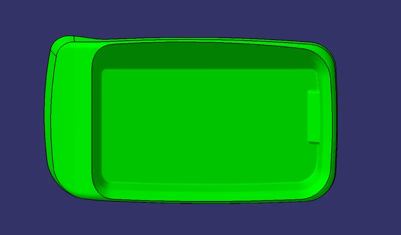
SIDE VIEW OF DRAFT ANALYSIS
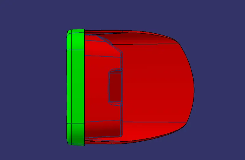
TOP VIEW OF DRAFT ANALYSIS
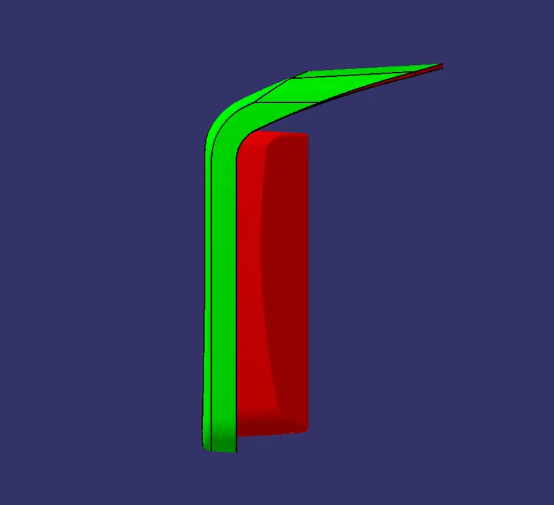
ISOMETRIC VIEW OF DRAFT ANALYSIS
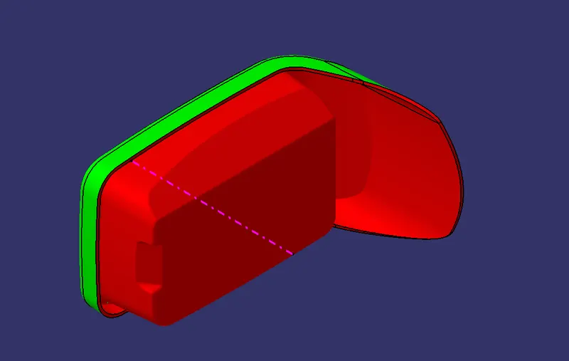
MULTIVIEW OF DRAFT ANALYSIS

CLOSED SURFACE BODY
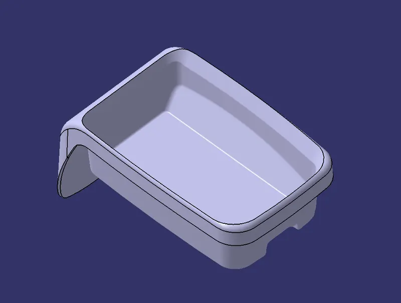
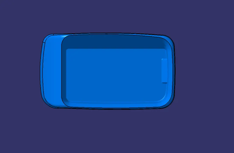
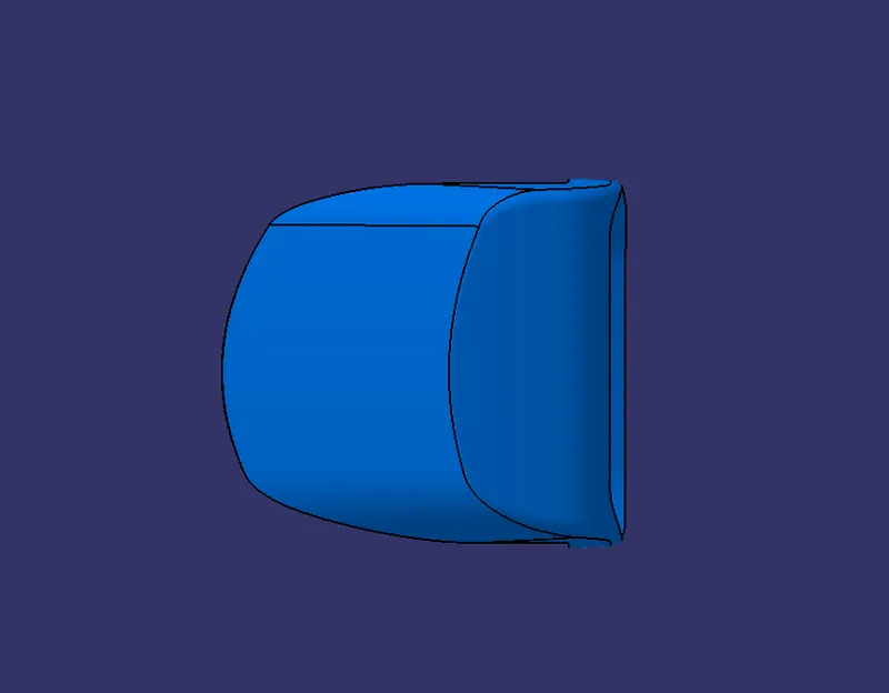
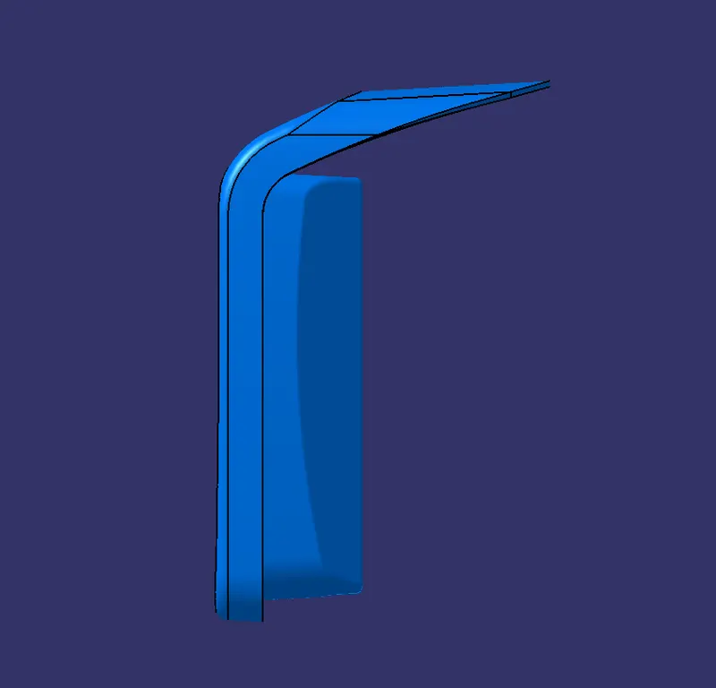
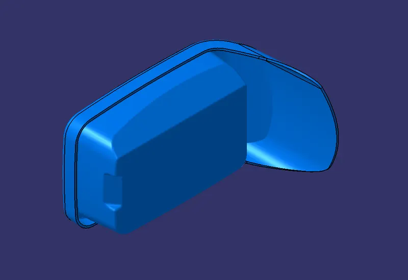
FINAL PLASTIC COMPONENT
FRONT VIEW
SIDE VIEW
TOP VIEW
ISOMETRIC VIEW
FEATURE TREE:-