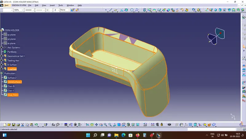
Week 8 - Challenge 3 - Coin Holder Design
Tooling axis creation:
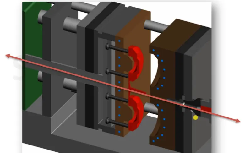
- In Molding, machine arrangement is given to open the mould along a direction which is known as Tooling Direction.
- Analyse the part from all views and choose the best suitable tooling Axis direction.
- Check for a Hollow Bin like area or Hole. If any of them may exist work on those features for creation of Tooling Axis.
- Check for any tapered V shaped areas, such shapes can be easily cleared in the tooling axis direction.
- In component "Coin holder" , we have bin like shape, hence we can clear the hollow portion in the core (downside) and the B side in the cavity (Upside).
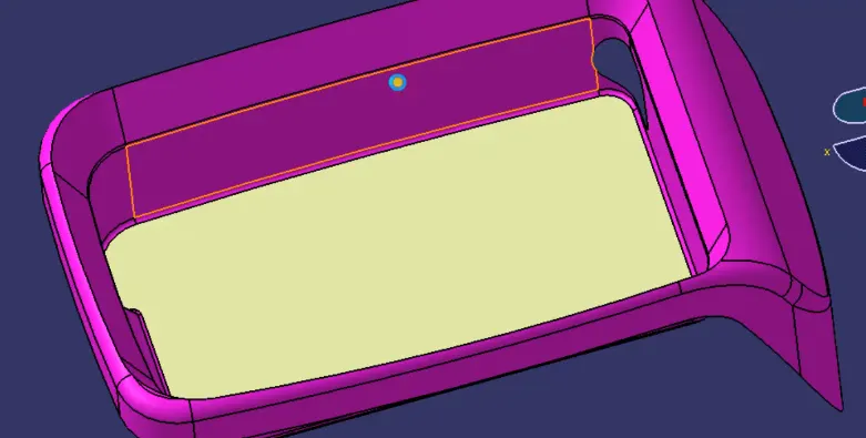
- Next, Extract the Base surface of the Coin holder, and create a point on the surface. Put distance as "0" to create a point at center.
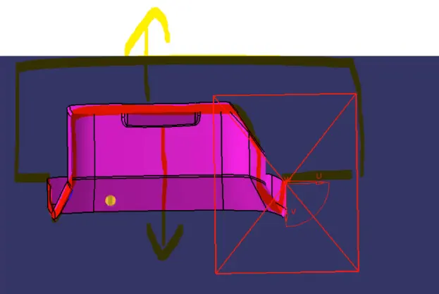
Create an Axis sustem on the point. - Use the Intersection command to get the cross section of the Class A. We do this to find out wether the side walls are at an angle.
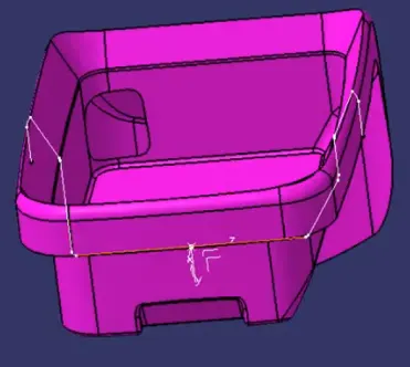
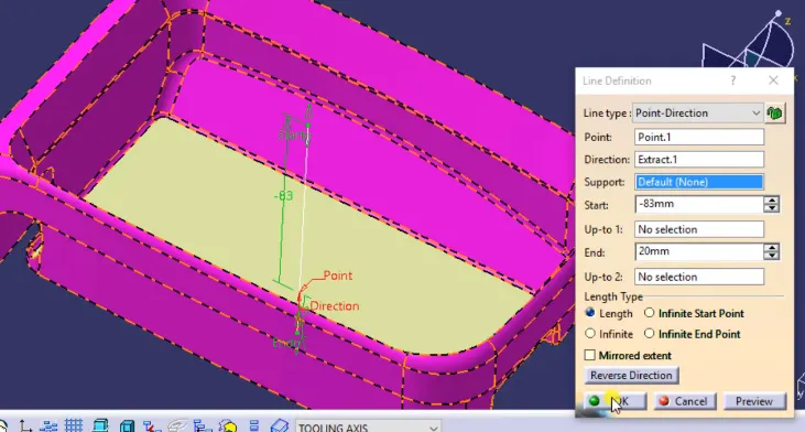
- In the Class A of Coin holder, we find that the side walls are at 90 degree with the base. This is not an ideal condition, some draft should be provided.
- Product engineers are not allowed to make changes to the class A, hence convey the information to the concerned person who has created the Class-A.
- In such situation where the side walls are symmetric and alomst 90 degree to the base we make the tooling axis perpendicular to the Base.
- Create a normal line using "Point-Direction" method. Select the mid point we had created earlier and make a line perpendicular to the Base. This is our tooling Axis.
Thickening Class A or Creating the Class B and Class C surfaces.
Class B:
- Fillets are difficult to thicken and give imporper results, hence we extract the flat faces and offset them, later create fillets accordingly.
- Distingush the model into different flat faces, and give separate colour to each face group.
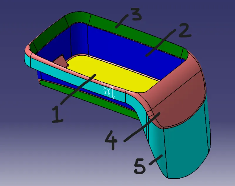
- Extract each of the flat faces individually using Extract / Multi extract.

- Untrim the extracted faces.

- Extrapolate each surface individually.

- Trim off the excess surface.

- Offset by distance of 2.5mm.
- Create offsets of all the flat surface and create the final trim.
- Provide radius on B surface according to the Class A surface.
Class C:
- We use Sweep Command for creating Class C surface.
- Create a Boundary on the Class A surafce and extract all adjescent faces. Below images are of the Selected adjescent edges.
- Creat sweep using option " with reference suface". Select the Boundary and Class A. use angle 90 degree with the adjescent surfaces.
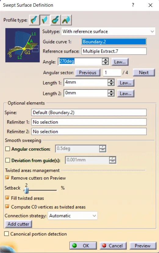
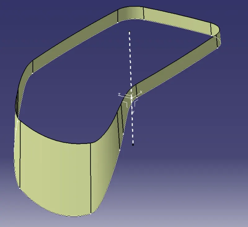
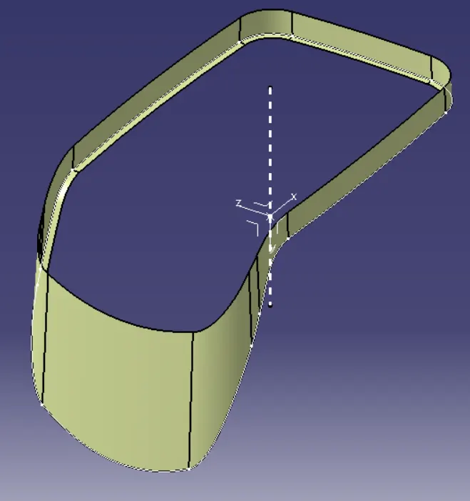
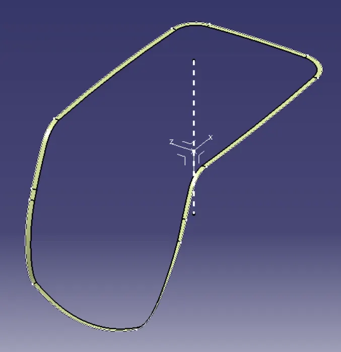
(Adjescent edges to the boundary of Class A and CLASS C surface Sweep) - While sweeping always remember sweep with the Class A surface.
- Further if the Class C surface doesnot intersect with the Class B, We can extrapolate the Class B.
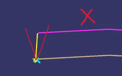
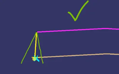
- Extrapolate Class B surface to match with the Class C surface and Trim to get a closed feature.
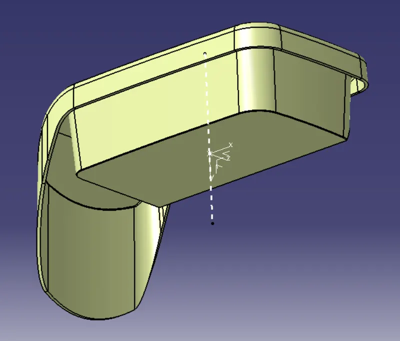
Creating a Solid Thickened part.
- To check wether the Thickened surfaces have formed properly use the boundary command, if the command fails then we have a properly closed surface or else the boundary will indicate where we have open edges.
- Use the Closed surface command to create a Solid.

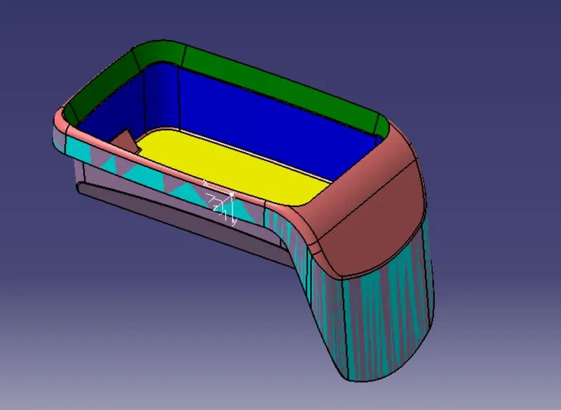
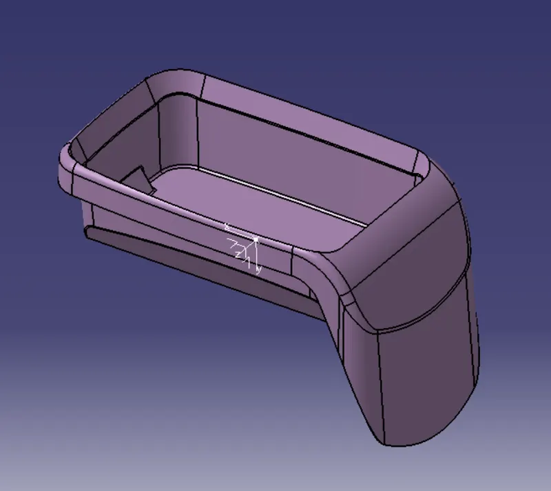
Final Model with Tree Structure: