Week 8 - Challenge 3 - Coin Holder Design
Coin holder
The initial step is to check for any discontinuity in the class A surface model using Join or Boundary option.
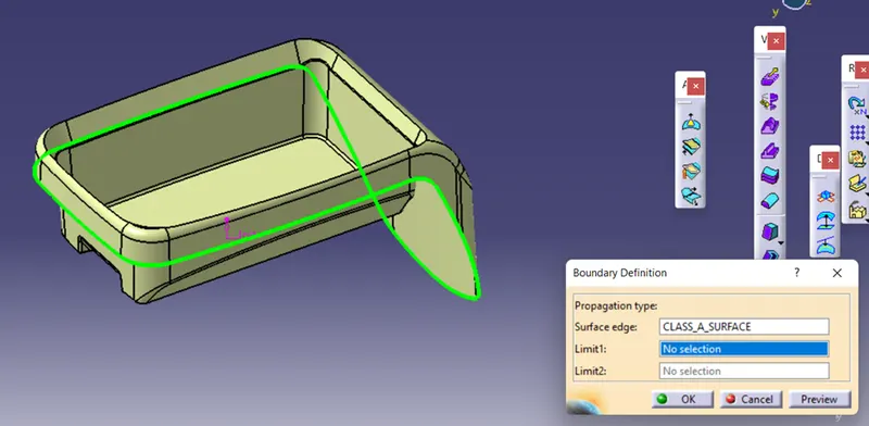
Here only the outer boundary line is found. There is no discontinuity between the surfaces.
The next step is to define the tooling direction.
Creating a midpoint on the bottom wall surface and an axis system placed on that point.
Y-direction reference axis:
Intersecting the class A surface with the YZ plane and extending two lines. Bisecting those two lines to create a reference axis for the Y-direction of the component.
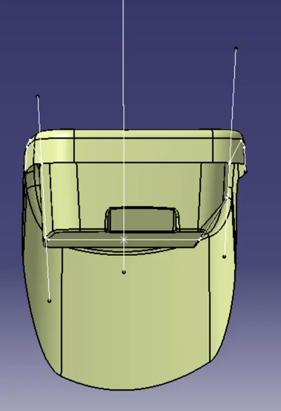
X-direction reference axis:
The next step is to define the reference tooling axis for the X-direction. Intersecting the plane XY with class A surface
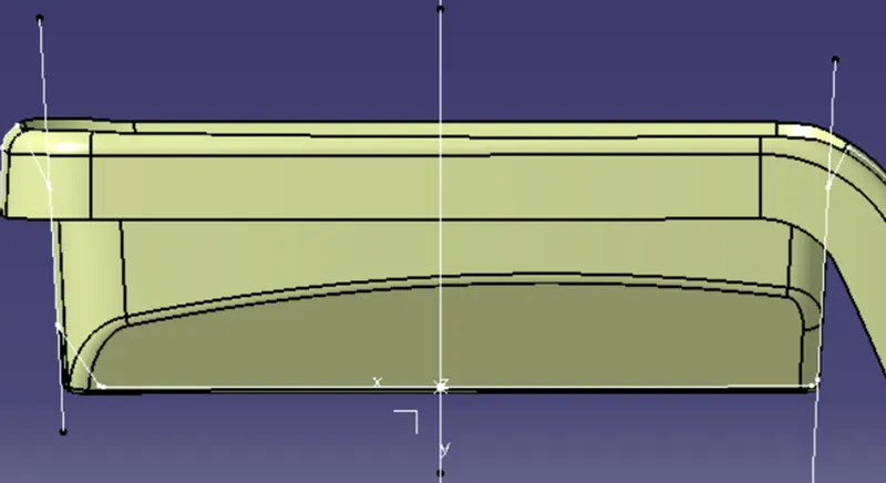
After that Bisect the X-direction reference axis with the Y-direction reference axis to get the tooling axis
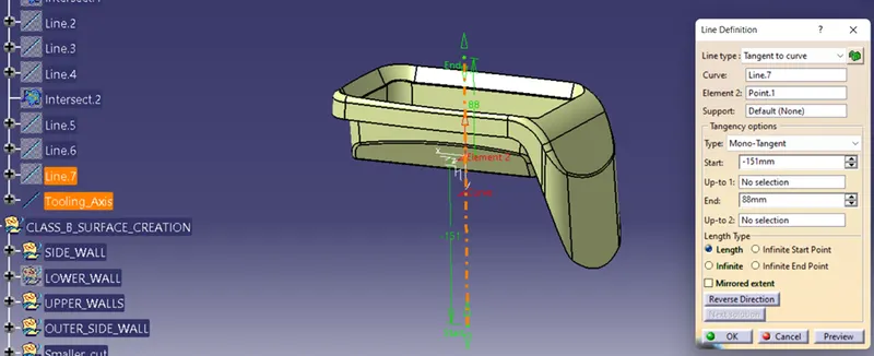
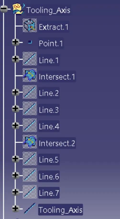
Draft analysis on Class A surface:
Draft analysis is performed on class A surface to check the draft angle's of each faces
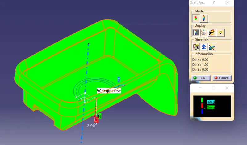
Green color on the class A surface denotes- Draft angle 3 degrees and above.
Other codes on the dialog box
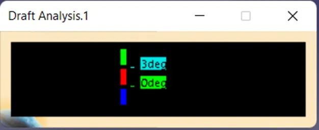
Red denotes- 0-3 deg angle
Blue denotes- Less than 0 degree
Class_B_Surface_creation:
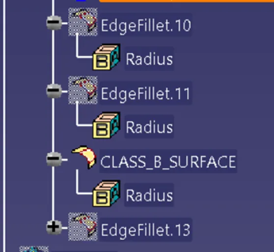
Extracting the faces from class A surface and offset to 2.5mm.
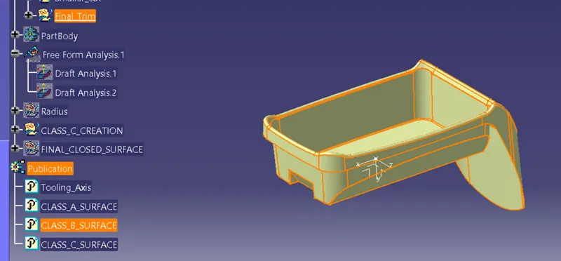
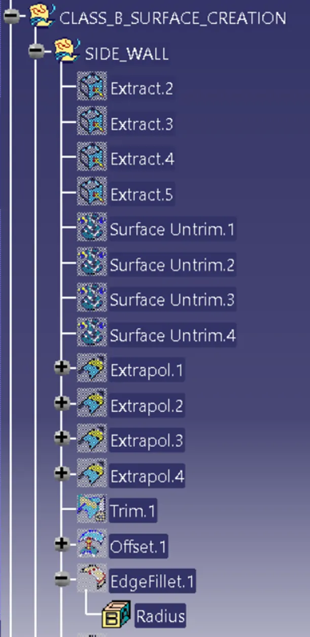
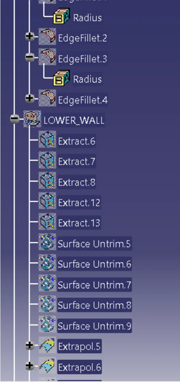
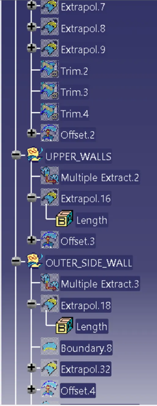
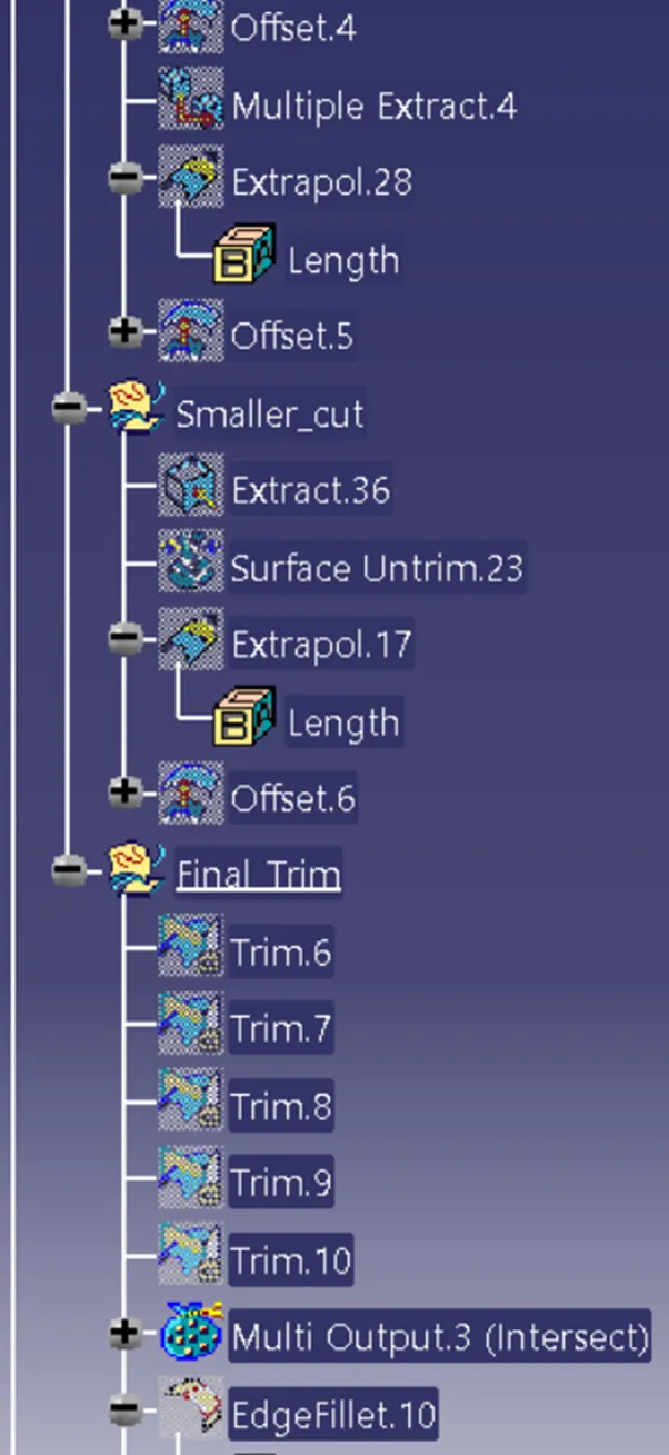
Class_C_Surface_creation:
Class C surface is used to connect class A and Class B to form a closed surface. Here the class C is perpendicular to the tooling axis
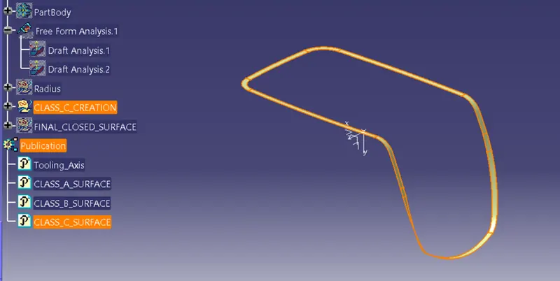
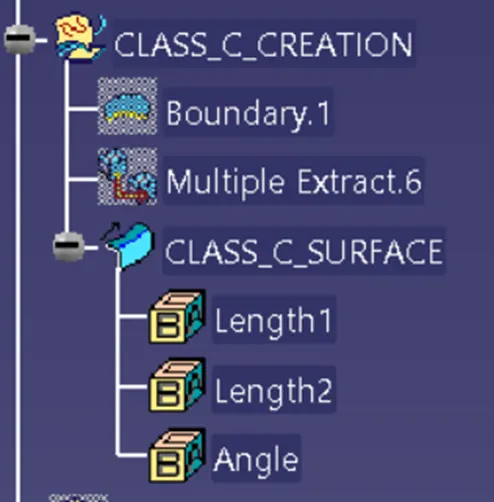
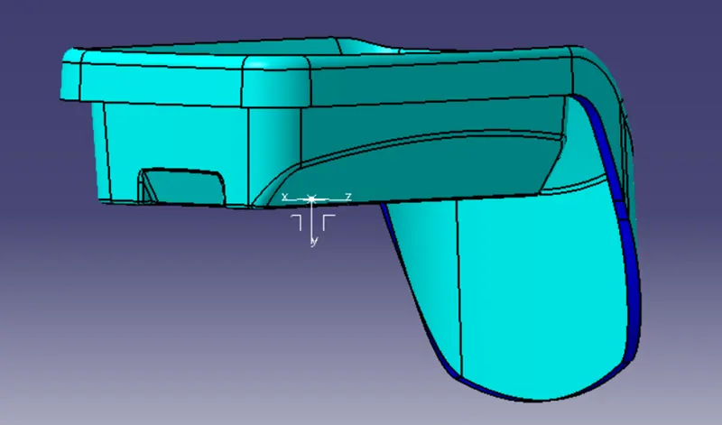
Joining Class A& Class C surface and trim with Class B surface to create a closed surface.
Creating a solid model:
Using the closed surface option in part modeling to form a solid model.
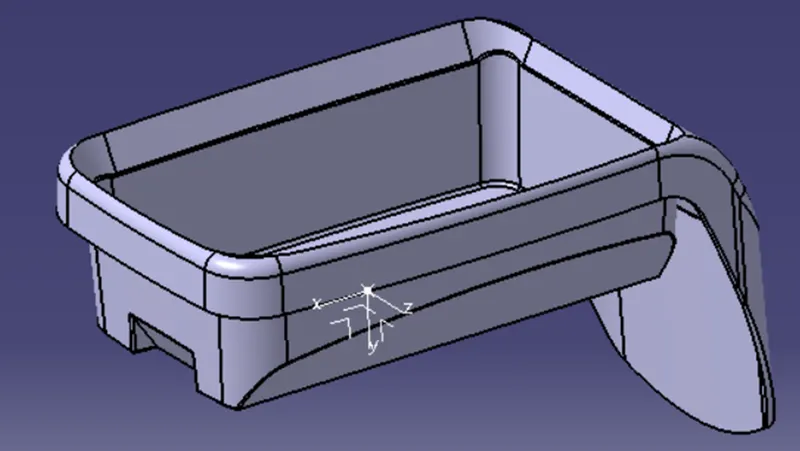
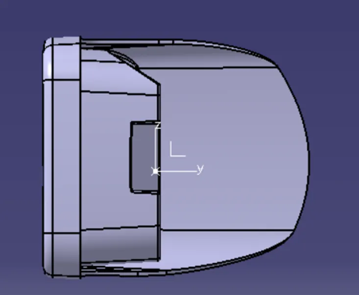
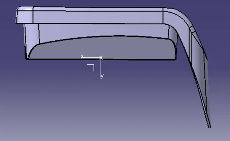
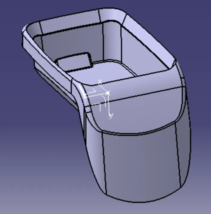
Draft analysis on the finished component:
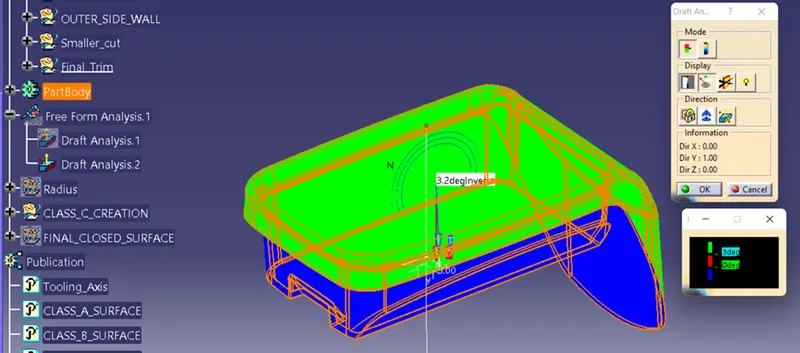
Green color denotes- Draft angle 3 degrees and above
Blue denotes- Less than 0 degree