Week 8 - Challenge 3 - Coin Holder Design
Objective: The main objective of this challenge is to understand the given class A surface for 'Coin Holder' and create class B & class C surfaces from the class A surface by using closed body surface commands.
TOOLING AXIS:
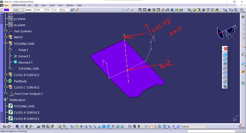
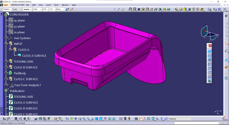
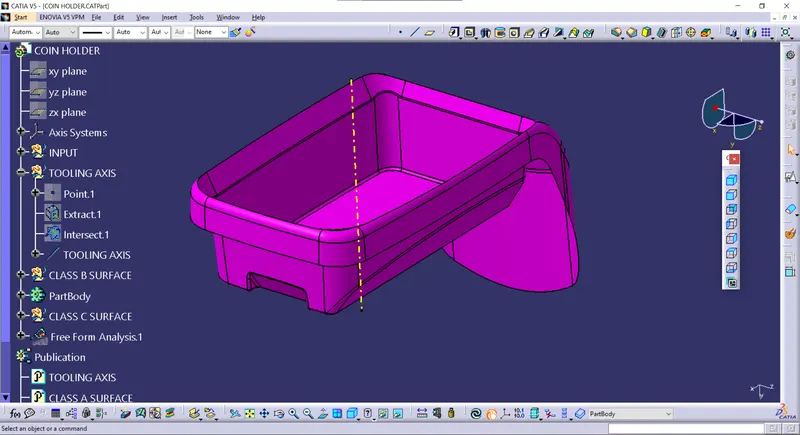
To create the tooling axis, I extracted the base surface and created a point on the centre of its surface and inserted an axis system to that point. Now, the intersection can be taken from the point in the yz axis on the class A surface. By understanding the intersection a line is drawn at the point on the surface by taking the reference of the extracted base surface. The created line is the 'Tooling axis' for the surface.
CLASS B SURFACE:
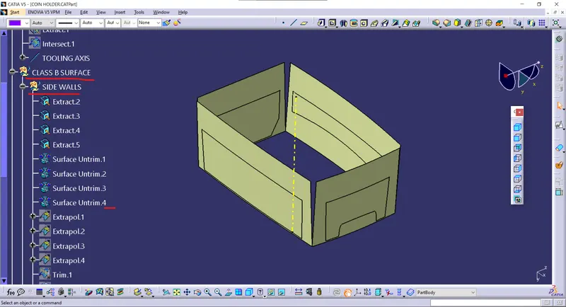
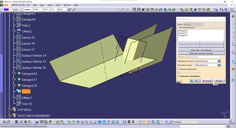
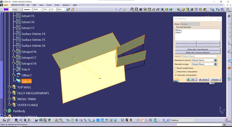
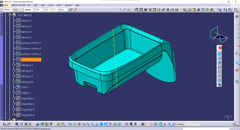
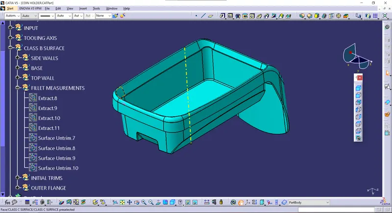
Class B surface is the 2.5mm offset to the class A surface. If we directly try to offset the class A surface, the CATIA show the pop-up error due to the fillets on the surface of class A. To terminate the errors, I individually extracted the surfaces of class A (Side walls, Base, Top walls and Outer flange) and untrimmed those extracted surfaces and filleted them with class A measurements with the addition of the thickness (2.5mm) of the body.
SIDE WALLS:
Extracts and untrims:
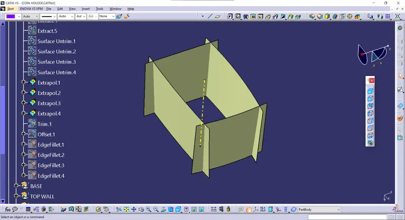
Extrapolate Side walls:
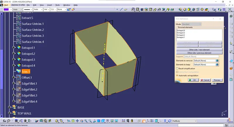
Side walls Trim:
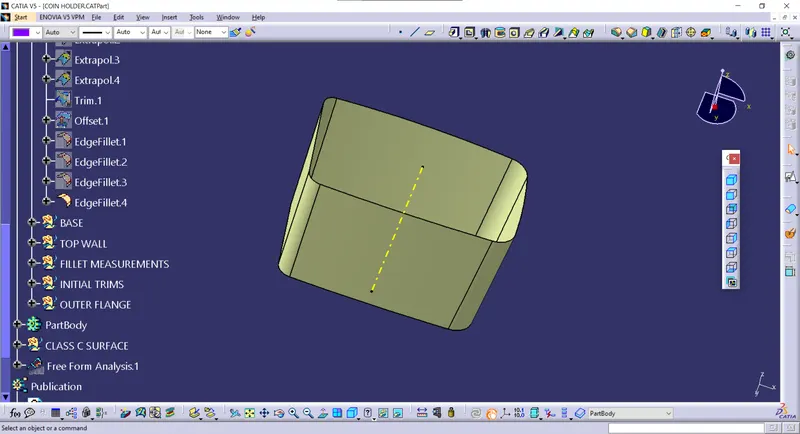
Fillets:
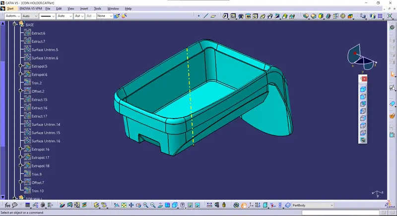
BASE:
Extracts and Untrim:
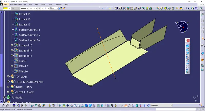
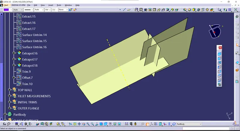
Extrapolates:
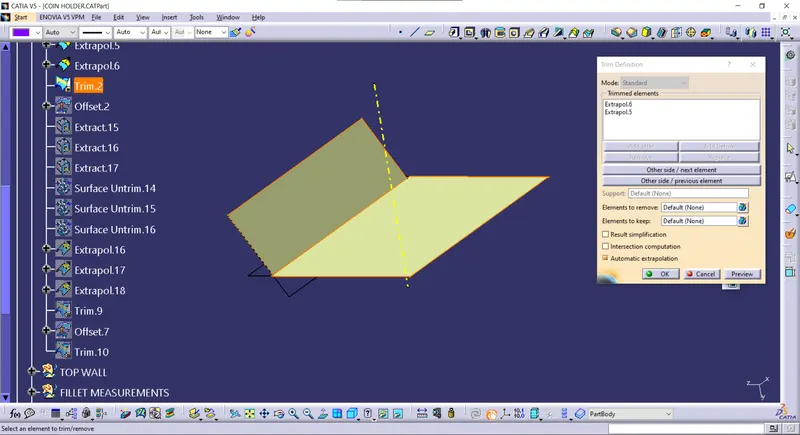
Base Trims:
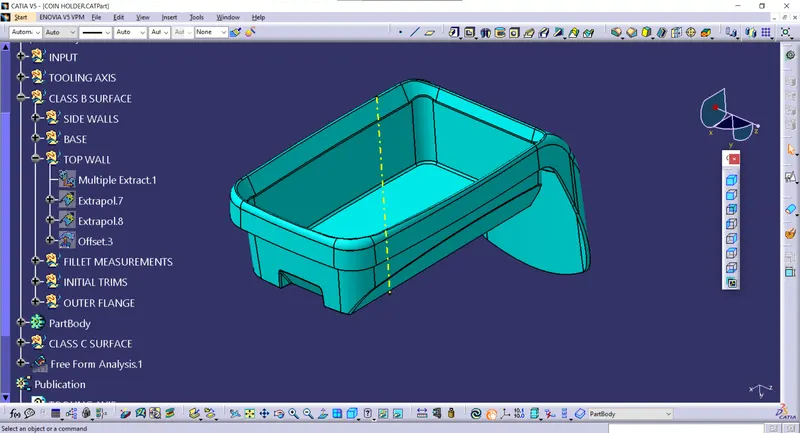
TOP WALL:
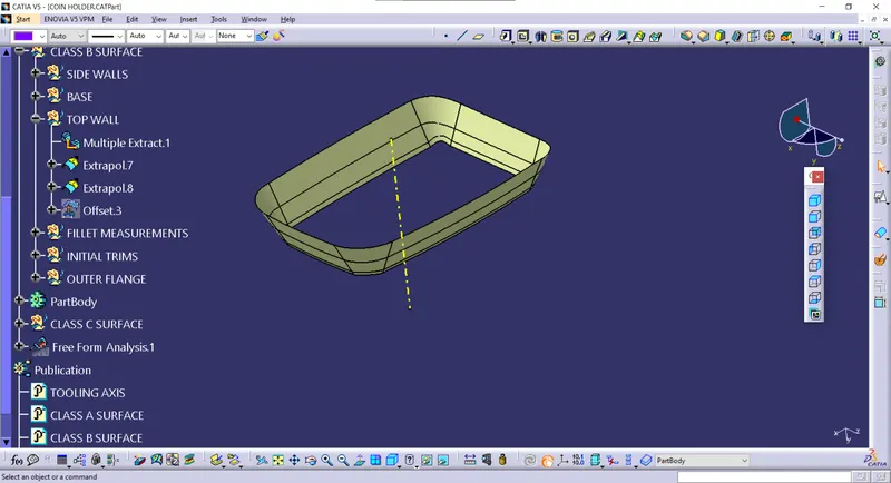
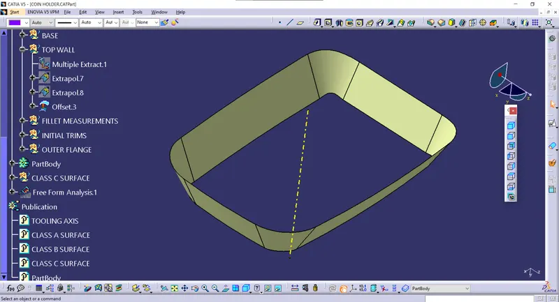
Multiple Extracts and Extrapolates:
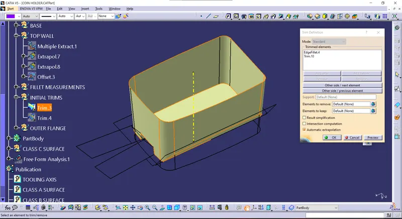
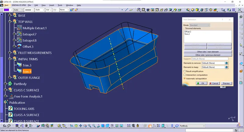
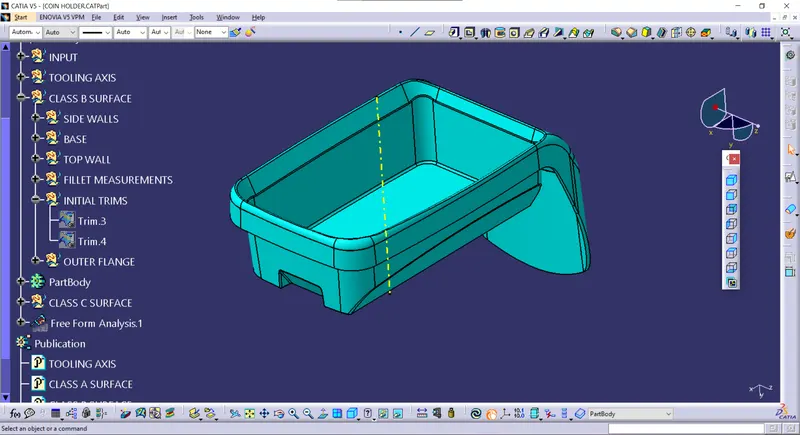
Initial Trims:
Initial Trims are to get the proper Class B surface from the extracts.
OUTER FLANGE:
Multiple Extracts:
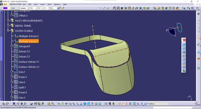
Extrapolates:
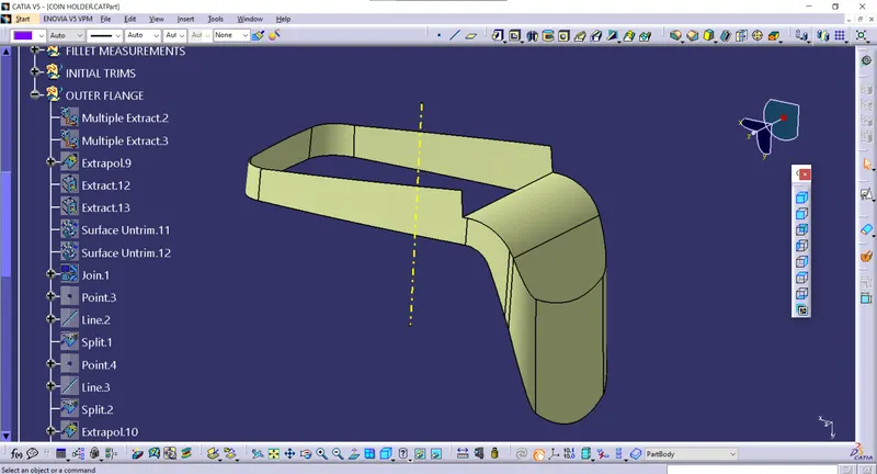
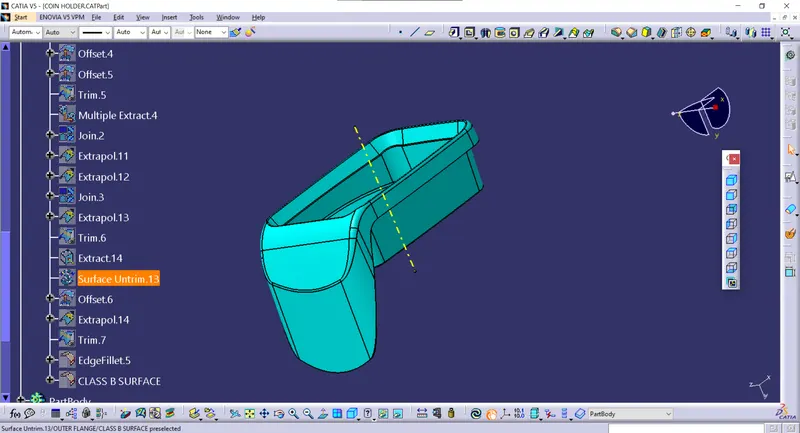
Trims:
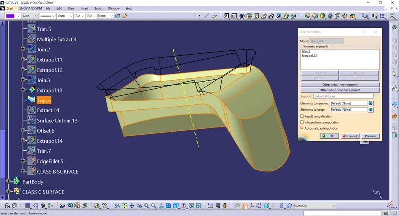
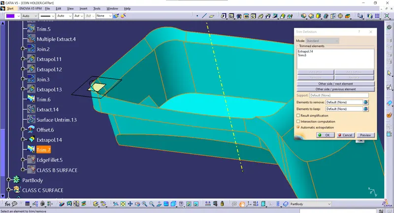
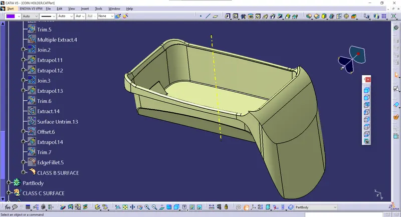
Complete Class B surface:
CLASS C SURFACE:
The Class C surface is the combination of both class A and class B surfaces, with the help of the class C surface we can able to make a complete closed body by joining all class A, class B and class C surfaces.
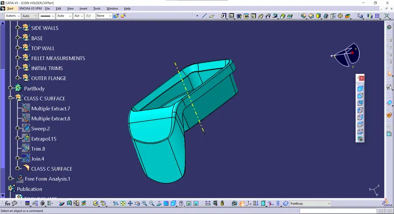
Here, The class C surface is created from the outer boundary of the class A surface. I used sweep command to create a class C surface. After creating the class C surface, I trimmed each other to get the exact 2.5mm thickness (or distance) from inside the class A surface to make a closed surface. Finally, I joined all the class A, class B and class C surfaces.
Multiple Extracts:
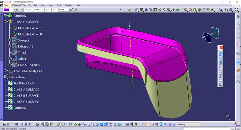
Sweep:
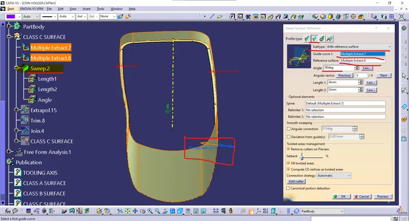
Trim with Sweep and class B surface:
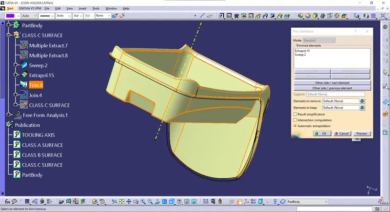
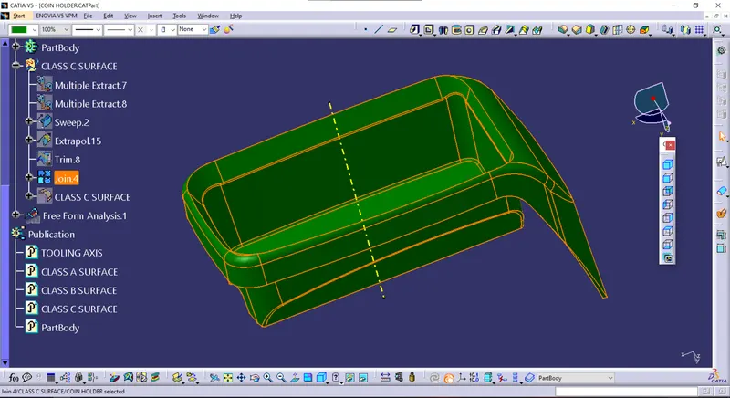
Closed body: (combination of class A, class B and class C surfaces)
To combine class A, class B and class C surfaces I used the join command to join and make a closed surface.
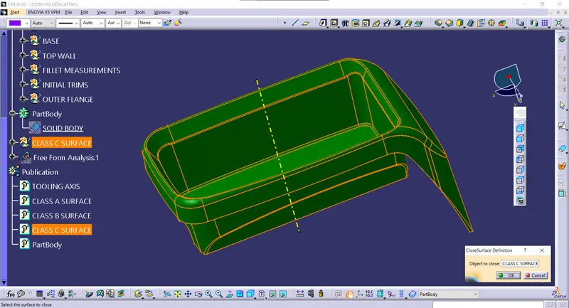
SOLID PART BODY:
The solid part body is created from the closed surface, created by joining all three surfaces (class A, class B and class C).
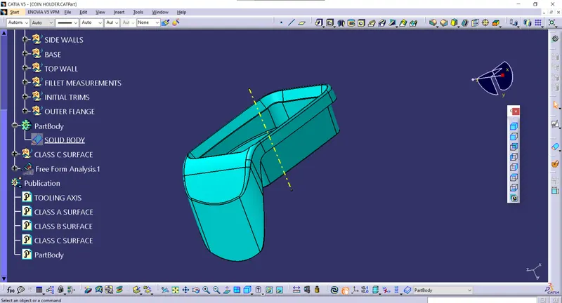
To create a solid body form a closed surface, we need to go to the part workbench. In the part workbench, I used the 'closed surface' command to thicken the closed surface to create a solid body.
DRAFT ANALYSIS:
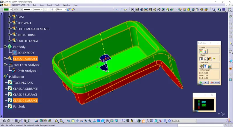
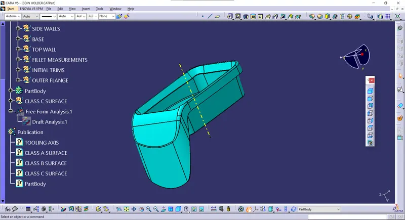
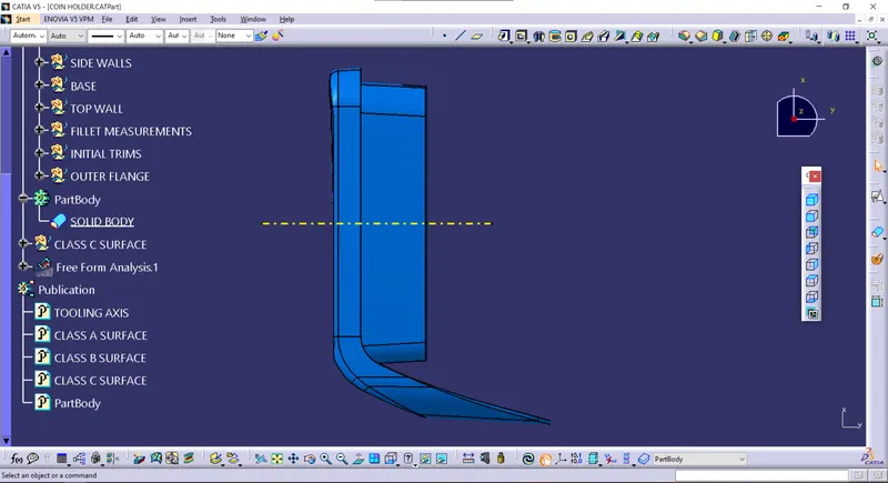
To perform draft analysis on a solid body, I used the 'featured draft analysis' command in the analysis toolbar. In the featured draft analysis, click on the compass and align it to the tooling axis, which we created in an earlier stage of designing the coin holder. Once the compass is aligned to the tooling axis click on the part body to check the draft angle at different surfaces.
The color bar in the draft analysis visualizes the green and red color. The surface draft angle greater than 3deg is highlighted with green color and the surface draft angle is less than 0deg will be highlighted with red color. Based on the compass alignment with the tooling axis, the colours may be swapped by inversing the draft direction, we can get the proper analysis. We can change the color bar color coding as per our requirements by customizing the colours.
TREE STRUCTURE:
INPUT:
Class A:
TOOLING AXIS:
CLASS B SURFACE:
SIDE WALLS:
BASE:
TOP WALLS:
FILLET MEASUREMENTS:
INITIAL TRIMS:
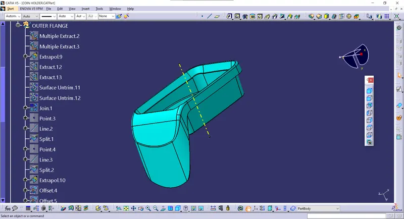
OUTER FLANGE:
CLASS C SURFACE:
PART BODY:
FREE FORM ANALYSIS: (DRAFT ANALYSIS)
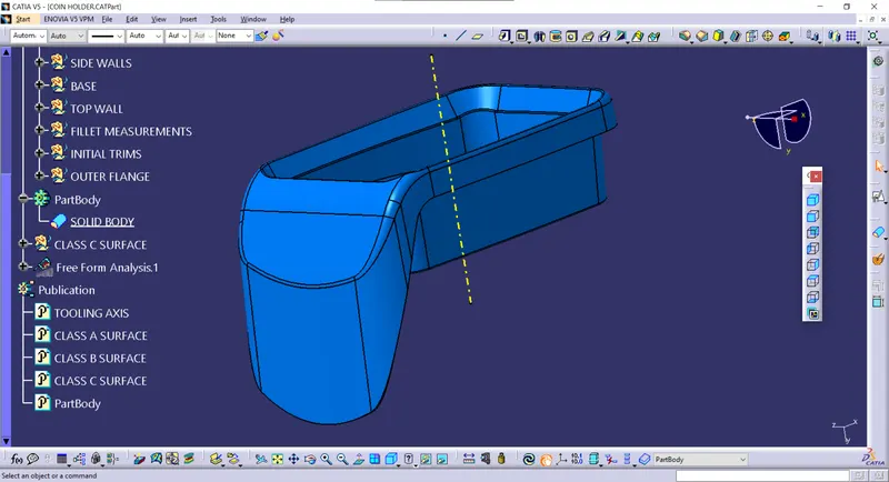
SOLID PART BODY (COIN HOLDER): [DIFFERENT VIEWS]
ISOMETRIC VIEW:
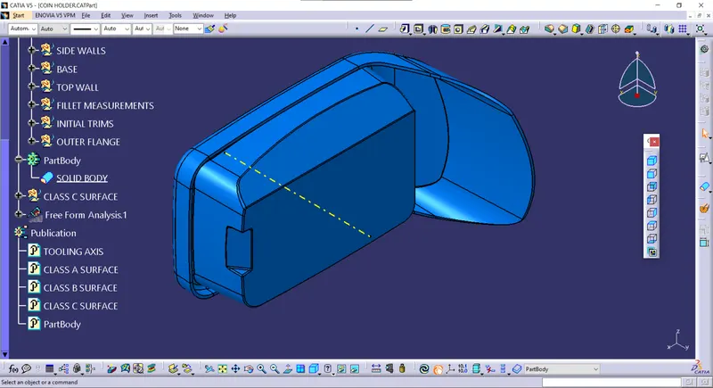
FRONT VIEW:
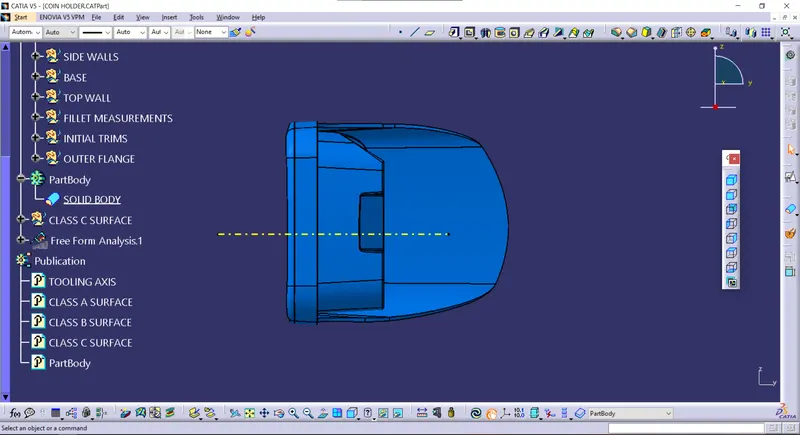
BACK VIEW:
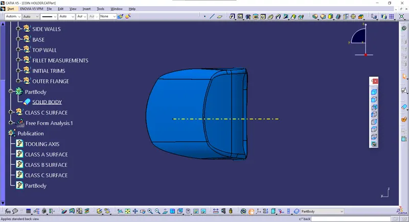
LEFT VIEW:
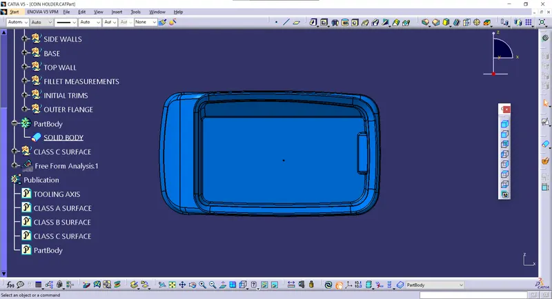
RIGHT VIEW:
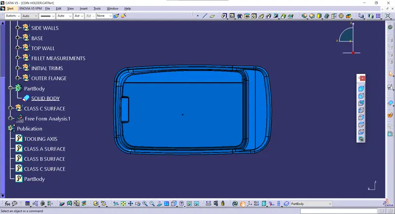
TOP VIEW:
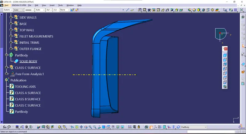
BOTTOM VIEW:
'The required CATpart for coin holder is enclosed in the below browse section'.