AIM:
To Create the Coin Holder Plastic component through the given Class-A surface. To begin with, the tooling axis for the given Class-A Surface should be created meeting the requirements of the draft angle and at the end perform the Draft analysis on the model.
Take the Thickness of the component to be 2.5 mm
OBJECTIVE:
To create the Base Bracket Plastic from the given Class A.
To ensure the all the sketch and tools in the Geometry set.
Give the proper name of the Geomatry set.
Create the Class B ad Class C.
The objective of the project is to design the coin holder and to do a draft analysis for it by creating the required tooling direction with the help of Bisecting method.
INTRODUCTION:
With draft analysis, you can verify draft angles, examine angle changes within a face, as well as locate parting lines, injection, and ejection surfaces in parts.
Drafts are defined on molded parts to make them easier to remove from molds. There are two ways of determining the objects to draft: either by explicitly selecting the object or by selecting the neutral element, which makes the application detect the appropriate faces to use.
To create the Geomatry set with proper name and sub geomatry set also.
A positive draft means the angle of the face, with respect to the direction of pull, is more than the reference angle. Negative draft. Displays any faces with a negative draft, based on the reference draft angle you specified.
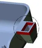
TOOLIN AXIS:
The direction in which the mold or core and cavity opens is the tooling axis. Connectivity of Class-A surface: Checking the connectivity of the surface, this can be done by creating boundaries or by simply using the join option such that any openings can be easily visualized.
Create the Tooling Axis from the class A surface. First extract the surface and then create the point.
Create point on the Extract.
Tooling Axis create by the help of point.
Draft Analysis of the Class A to the initial stage.
Draft Analysis with 3deg.
Dradt Analysis with 0.4 deg.
After checking the Draft analyse Create the Class B and Class C.
CLASS B:
Start with the base of the surface.
Extract the all required surface of the base.
And then Untrim it the Extract.
Extrapolate it.
offset it with 2.5mm.
We get like this.
Trim it
Likewise create to all surface of the components and untrim it and Extrapolate and pffset it.
Create the Class B surface and fillet it.
Get the CLASS B
Creating Class C From the Class A.
Extact the Edge and Surace from the Class A.
Create sweep by this two Extracrion.
CREATE THE CLASS A B C:
Join Class A with Class C.
Class A C are Trim with Class B.
Final surface are
Go to part workbench Make a solid part from the surface by the close view command.
TREE STRUCTURE:
DRAFT ANALYSIS:
3D PART ORIENTATION:
ISOMATRIC VIEW:
FRONT VIEW:
SIDE VIEW:
TOP VIEW: