Coin Holder Design
AIM:-
Create the coin holder plastic component through the given Class A surface.
INTRODUCTION:-
CLASS-A SURFACE: a surface made by the designer which is given as an input to the plastic modeler to work on. It is aesthetic surface and the outer most surface.
CLASS-B SURFACE: a surface below a certain thickness from the class-A surface is class-B surface. This is the surface that contains engineering aspects of a model.
CLASS-C SURFACE: a surface that joins class-A and class-B surfaces is class-C surface.
OBJECTIVES:-
- Checking continuity of class A surface.
- Deciding feasible tooling direction & creating tooling axis.
- Performing draft analysis on class A surface.
- Creating class B surface from given class A surface.
- Creating class C surface to join A & B class surface.
- Creating solid feature by using closed surface.
- Performing draft analysis on final plastic component.
Procedure:-
We will be recieving a styling class A surface from styling team who deveopes it from a concept sketch to aesthatic class A with styling software for eg:ALIAS.here our work is to get the class A and import it to the design tool to develop Class B & C surfaces. Checking Class A input for imperfections. The input Class A surface is checked for the discontinuities and joined together to get complete Class A surface as one.
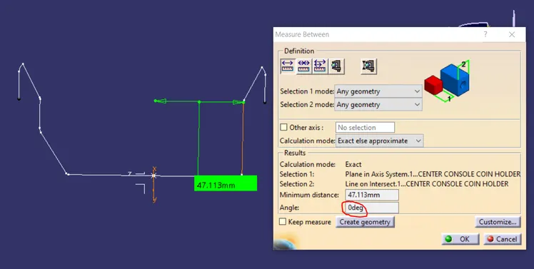
As class-A surface is made by other designer only he is authorized to make changes, so we look over this to complete the coin holder for practice.
Now we go to insert< analysis< draft analysis and follow usual procedure to do the analysis.
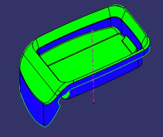
Align the compass and click on the surface and as expected the model is mostly in red color i.e. negative draft with respect to the axis.
To correct it to as best as we can we moved the compass a bit till we got most of the surfaces in green and lock that position.
After hitting ok, we change the direction of the line from z axis to compass direction. The axis will align itself accordingly.
Tooling Axis Creation:-
i. Main Tooling Direction:
In this model the walls of the model are perpendicular to the Y axis therefore the tooling axis is created along the Y Direction. Draft analysis highlighted the walls blue in colour as they were exactly parallel to Y axis which means they have 0 degrees draft.
ii. Side Core Tooling Axis:
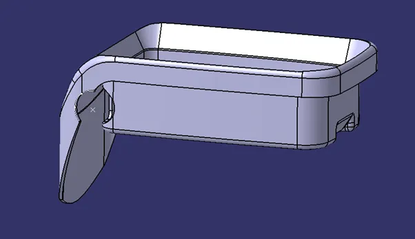
A point is created near the hole using the by extracting the arc like feature on the outer flange of Class A Surface.
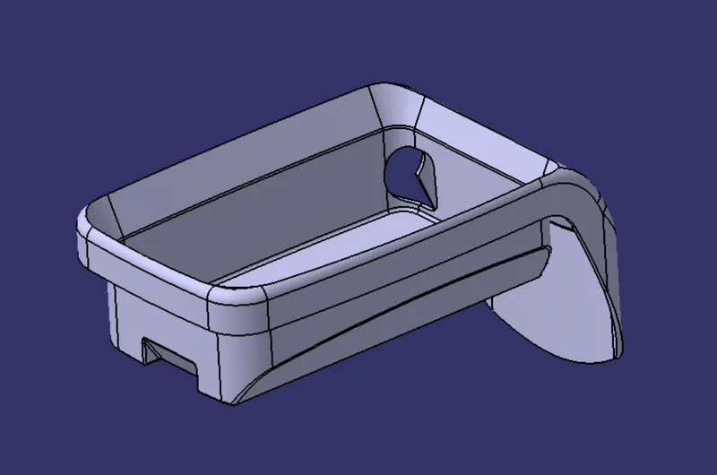
FINAL MODEL:-
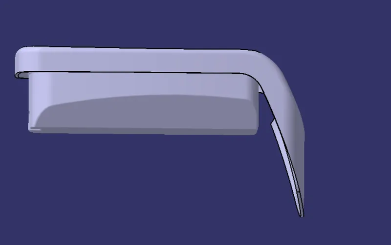
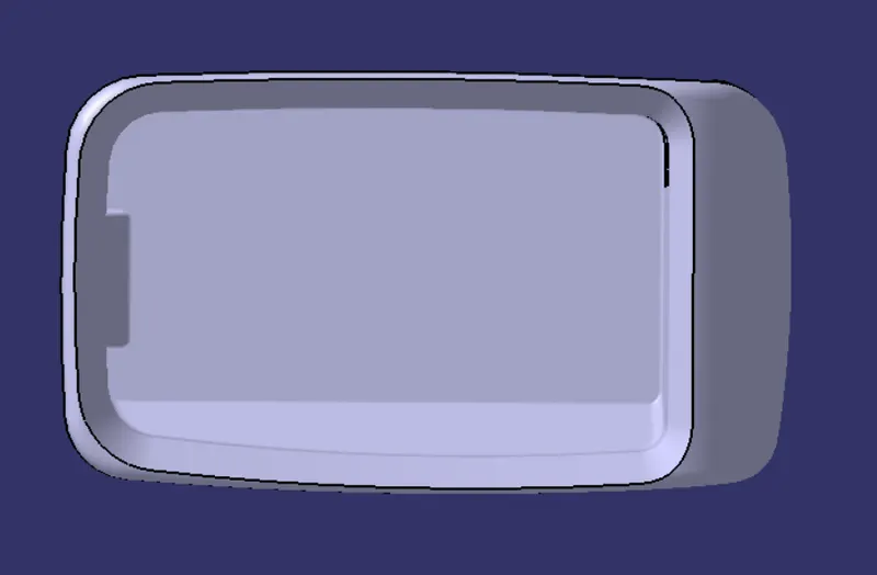
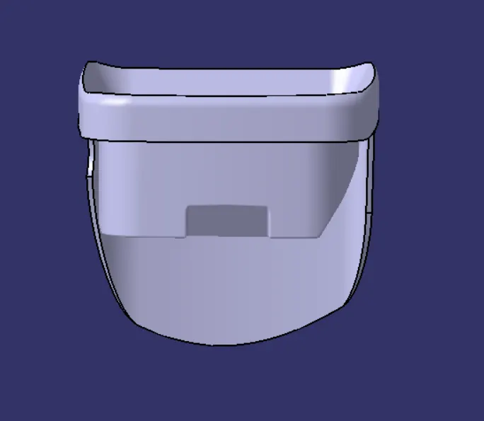
CONCLUSION:-
Thus the solid model of the coin holder is created and draft analysis is performed on the model using the main tooling direction and the side core tooling direction.