Week 8 - Challenge 3 - Coin Holder Design
COIN HOLDER DESIGN
AIM:
Create the Coin Holder Plastic component through the given Class-A surface. To begin with, the tooling axis for the given Class-A Surface should be created meeting the requirements of the draft angle and at the end perform the Draft analysis on the model.
Take the Thickness of the component to be 2.5 mm
OBJECTIVE:
- To create the Coin holder Plastic component through the given Class-A surface. To begin with, the tooling axis for the given Class-A Surface should be created meeting the requirements of the draft angle and at the end perform the Draft analysis on the model.
- To create the Class B and Class C Surface of the component.
PROCEDURE:
- Tooling axis is the direction in which the mould opens or the core cavity opens. By providing tooling axis to the component we can also do the draft analysis of the component. Draft analysis is performed on components where the ejection of materials happen after the material is made inside the tools.
- Class B surfaces are the secondary surfaces that you can see sometimes, but are less important.
- Class C surface are the surfaces which connects the class A and Class B surfaces
METHODOLOGY
- Skin data would be provided to us by the styling team to us.
- The first step is to check the continuity of the class A surface. This is to ensure that there is no gap between surfaces. If we find any then we should fix that first.
- The second step is to find the tooling axis of the component.
- Then we can make the component by creating the class B and class C component.
- After that we can do the draft analysis of the component.
Tooling axis creation:
- Injection moulding includes Core, Cavity, and Sliders to make a plastic product.
- Core, Cavity, and Slider move/side in a particular direction which is called Tooling Axis.
- Tooling axis can be made using either by Bisection method or Plane as a reference.
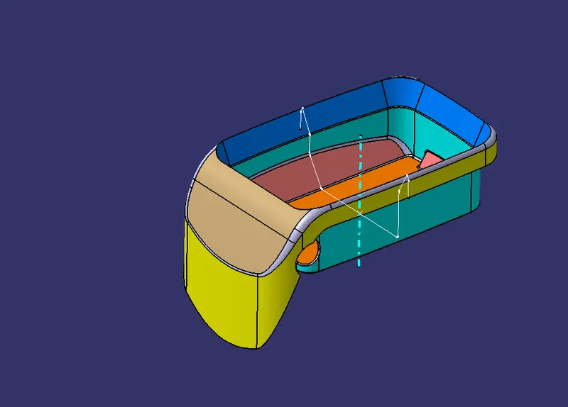
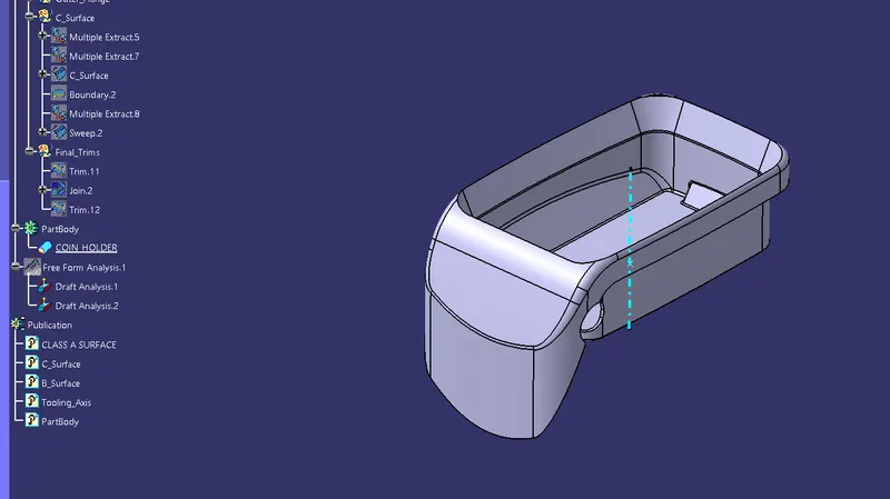
Generally tooling axis is created using bisecting line or plane method. But in the components where it has a bin, then the tooling axis is considered as a line normal to the base surface of bin. Same is done with this component. A line normal to base surface is created and considered as tooling axis.
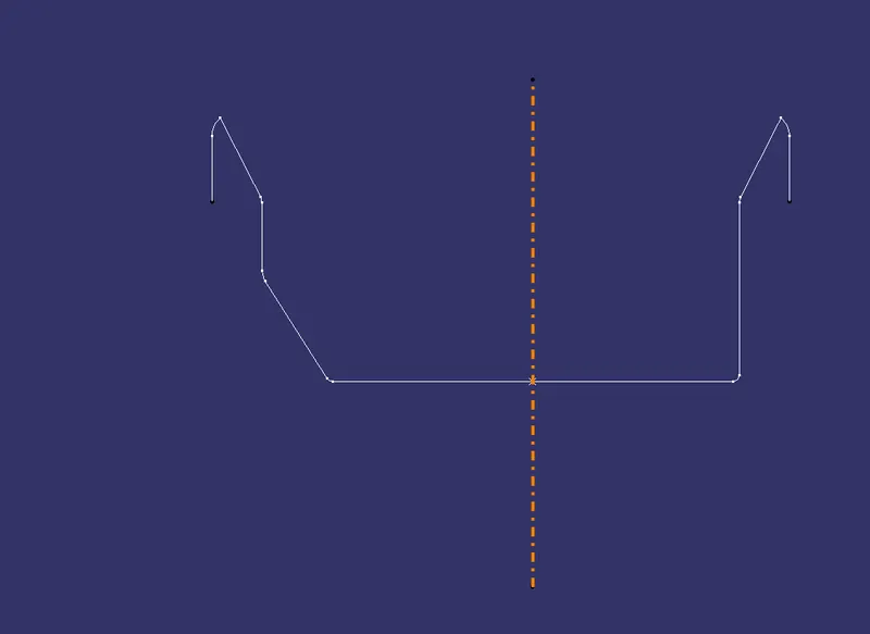
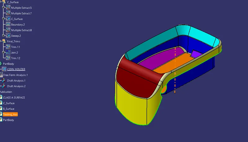
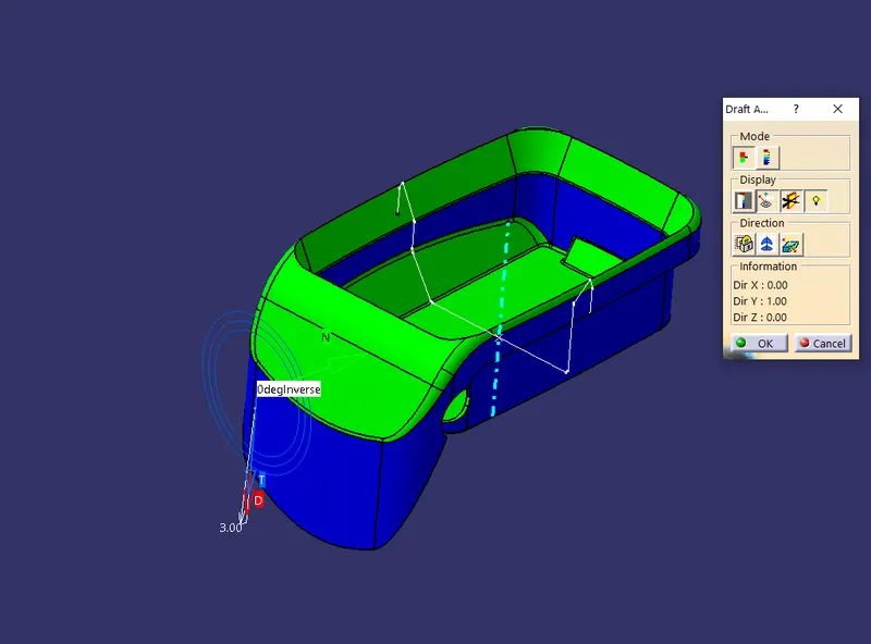
Draft analysis is performed on class A to check the Manufacturability of a component with the tooling axis. During draft analysis, it was observed that bin walls are having 90 degree angle with base. There is no minimum draft given to the walls. Since we are not authorised to make changes in class A surface, we can inform class A designer to give minimum draft to walls.
Since we have received this surface, we will continue to design using this class A.
Draft analysis of Class A:
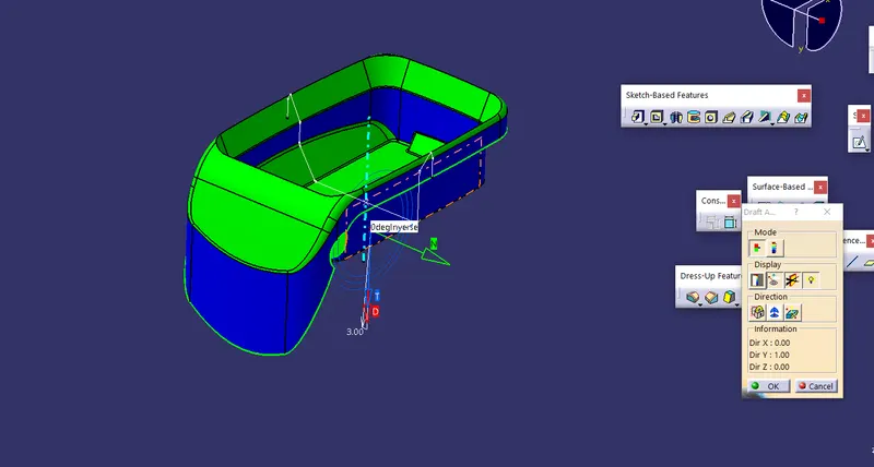
After creating a tool axis we do the draft analysis. Before drafting we have to make sure that in the view mode it is selected to the materials.
After selecting the feature draft analysis tool we drag the compass from its position to the tool axis. Then lock the compass. After that select anywhere on the component and it will give you the result.
We change the minimum draft for the component to 3°.
We can use the running point option to check the angle of the component.
We can even modify the colour according to our preference.
CLASS B SURFACE CREATION:
- From the Class A surface , Extracted a set of Surface for to create the Class B surface by Using Extract Command From Below Image.
- We can use extract command for all surface we needed for to create Class B Surface and then Use the Untrim command to restore the surface up to the limit.
- The Surface at which features like Side walls, base, top walls and Outer walls etc. are made to support external mountings is called Class B Surface.
- Class B Surface is made by simply extracting A Surface, offset it to desired thickness and trimming them together.
Since this is a complex component we separate some surfaces accordingly by giving some colours to the surfaces for our ease and then create the class B surface.
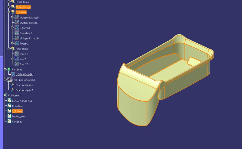
We start creating the class B surface for that we offset all the flat surface to 2.5mm and then we use the untrim tool to untrim the surface and then use the extrapolate tool to extend the surfaces. We do this the for all the separate sections we created and then we trim all the sections together.
Then we use edge fillet to fillet the corners wherever it needs.
CLASS C -SURFACE:
Class C surface is a connecting surface between Class A and Class B surface.
Draft angle and Tooling direction are considered while making Class C Surface.
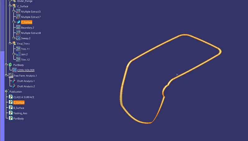
For this model the class C would be parallel to the horizontal plane because of the design of class A and class B.
We first extract the edges from the Class A surface with the help of which we create the path for sweep for class C and the we even extract the adjacent surfaces to use it as a reference plane.
So we select the sweep tool and in that we select with reference surface option and then we change the angle to 90° for it to be horizontal.
DRAFT ANALYSIS FOR FINAL PART BODY:
As we intersected to proceed we observed that the side walls are not given any draft. Hence we assume the axis normal to the base surface and parallel to side walls. This surely will create problems because a minimum draft has to be provided.
As class-A surface is made by other designer only he is authorized to make changes, so we look over this to complete the coin holder for practice.
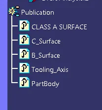
PUBLICATION:
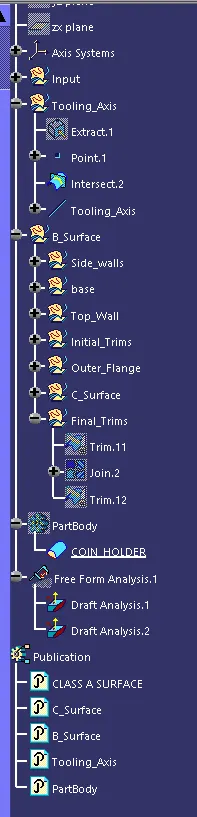
TREE MANAGEMENT:
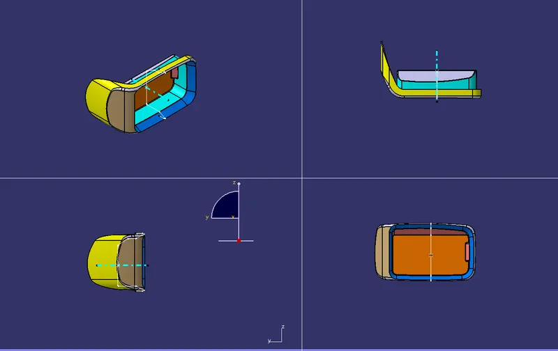
SOLID BODY:
CONCLUSION:
- The main tooling axis and the side core tooling axis have been created successfully using the feature draft analysis tool.
- Final closed surface has been created by using the trim and join faeture.
- The part body has been created by using closed surface tool.
- Draft analysis has been successfully done on the part body.
- Thus the above challenge has been finished with the proper input and all the required documents are attached.