Week 8 - Challenge 3 - Coin Holder Design
COIN HOLDER DESIGN
- Objective: -
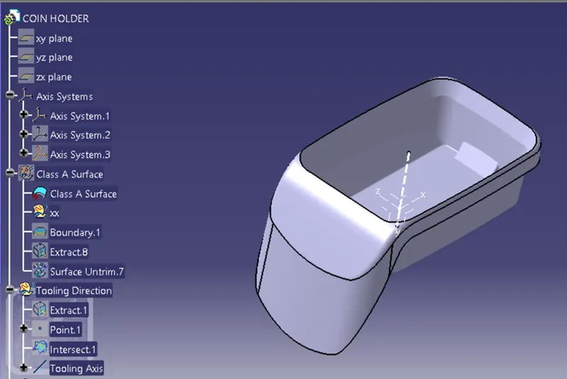
- Create the Coin Holder Plastic component through the given Class-A surface.
- To begin with, the tooling axis for the given Class-A Surface should be created meeting the requirements of the draft angle and at the end perform the Draft analysis on the model.
- The inner panel is subjected to the draft analysis to ensure whether it is satisfying the deep drawing requirements for the tooling direction that is created in the design.
- Perform the draft analysis for each component & reinforcement.
- Introduction: -
Product design starts with requirements. The designer will sketch the product based on your requirements. He then uses advanced CAD software to transform the 2D sketch into his 3D model with proper dimensions. Another important aspect of design is that any designed product is manufacturable.
Therefore, the designer's role is to design products that are easy and inexpensive to manufacture.
This is where Design for Manufacturing [DFM] and Design for Assembly [DFA] play an important role in product development.
The design development process continues until the design meets the customer's requirements.
The product to be developed this time is car back door.
TOOLING AXIS INTRODUCTION:
The direction in which the mould or core and cavity open is the tool axis. To easily visualize all openings, create boundaries or just use the connectivity option to see the connectivity of the surfaces. Visually analyse the optimal tool axis.
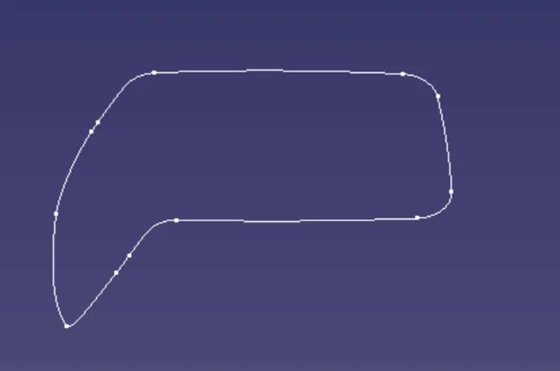
- First we performs a connectivity check to see if the given class A surface is It seems that there are no discontinuous boundaries.
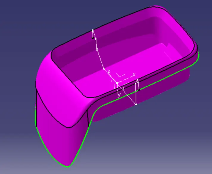
- After we Creates dummy tooling line for better clarity & can be used to create plane. This plane will help to create intersection (as shown in below image) by which we can creating lines.
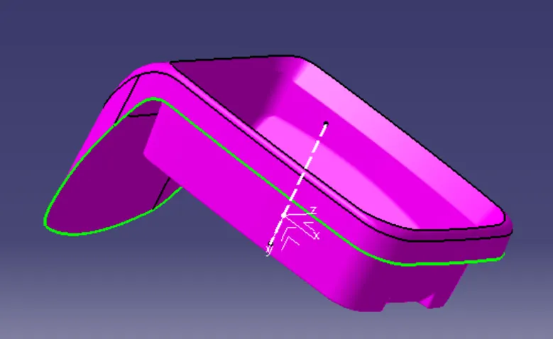
- Create bisecting line of from two construction line which created from the surface reference with intersection.
Mostly aluminium and steel are used in manufacturing, but steel is used in budget cars and is easy and cheap to manufacture following the stamping process.
PROCEDURE OF BASE BRACKET DESIGN:
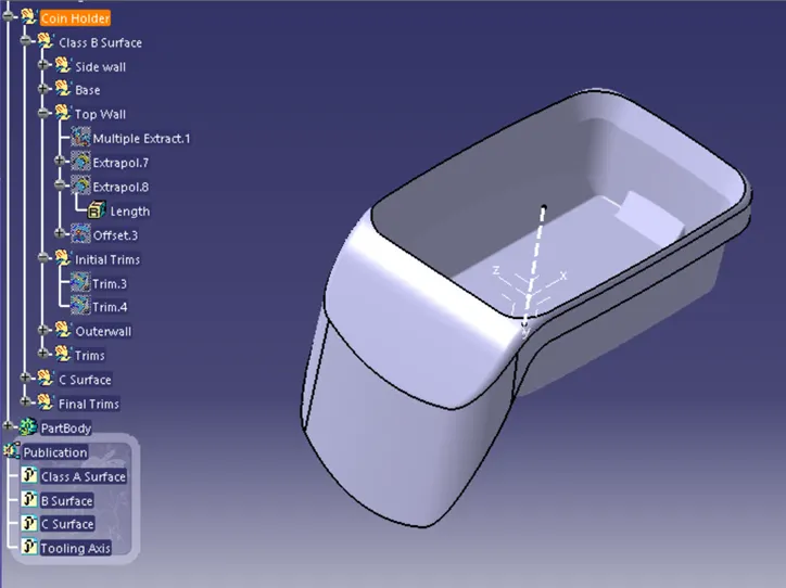
- B Surface Creation
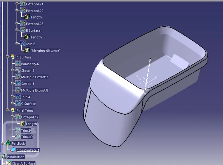
- C Surface Creation
- Trim C-A & then B surface formed complete base bracket in surface
- Use closed surface command to convert into thick solid
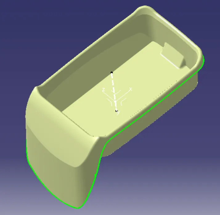
- B Surface Creation
- Cavity surface Creation
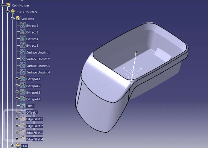
- Unhide the in the class-A surface.
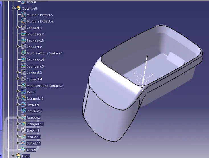
- Extracting the vertical surfaces from class-A surface.
- Un-trim all of the extracted surface.
- Extrapolate the un-trimmed surface.
- Trim the surface as per required shape.
- Repeat above steps for the next rib surface.
- Offset the created rib surfaces for 2.5mm inside to create CLASS-B SURFACE.
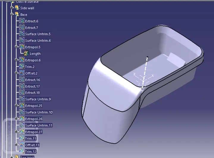
- Base Surface
- Extract the base surface from class-A surface.
- Un-trim the base surface.
- Extrapolate the base surface with point continuity & curvature.
- Offset he base surface for 2.5mm
- Complete class-B Surface
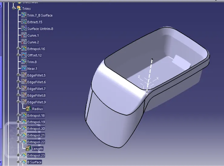
- Use trim command for join the ribs & middle surface first & then join with base surface to create single piece of class-B surface.
- Fillet the all required edges with proper & required fillet value.
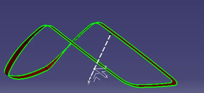
- CLASS-C SURFACE
- This is the interface for class A and class B
- Create a class-A surface boundary using the Boundary
- Use the Sweep command to create a Class C surface along the draft direction with a draft angle of 3 degrees to the tool
- Extrapolate and trim hole features from a class-A.
- CLOSED SURFACE
- Publish class-A, class-B, class-C surfaces and tooling axis.
- Join all the surface together.
- Create closed surface.
Trim Class-A & Class-C surface first then trim it with Class-B surface would form complete Base bracket.
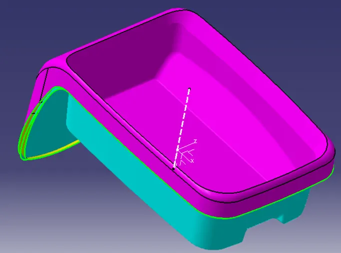
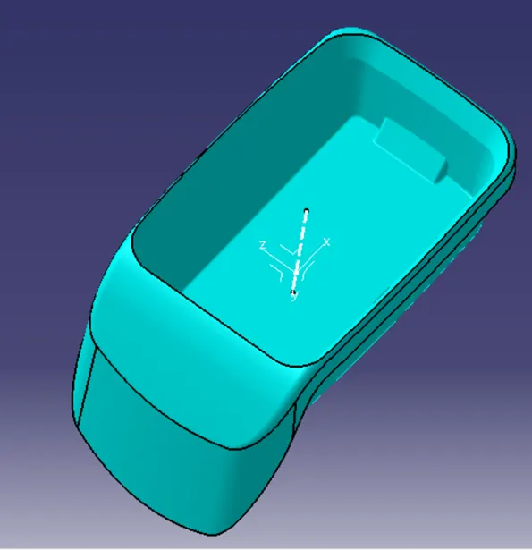
- Draft Analysis
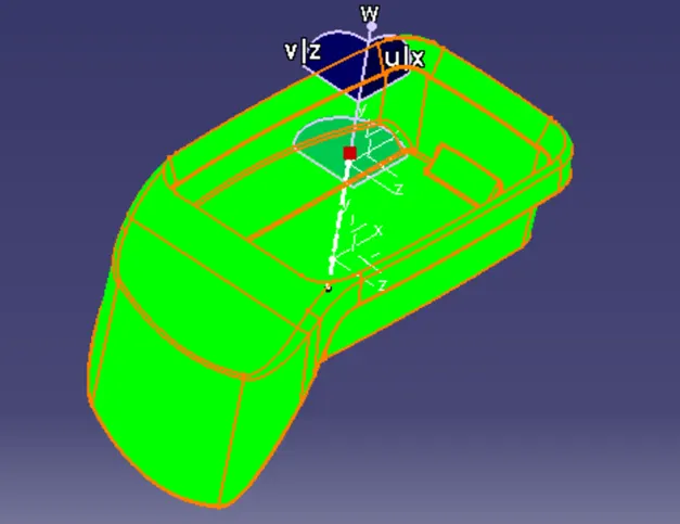
For Class A Surfaces
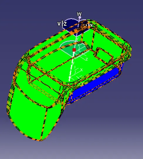
For Complete Part
Limiting draft angle = 3 degrees
Draft analysis from the selected tooling axis location.
- Conclusion: -
The Coin Holder Design is completed w.r.t Class-A surfaces & draft analysis also done completely with the help of CATIA software.