Week 8 - Challenge 2 - Switch Bezel Design
DESIGN AND DRAFT ANALYSIS OF SWITCH BEZEL
Aim: The aim of this project is to create a switch bezel plastic component using the given class A surface creating a tooling axis and draft analysis.
Design methodology:
- Insert the given class A surface of the switch bezel in CATIA software.
- Creating the tooling axis for the switch bezel
- Creation of class B surface.
- Creation of class c surface.
- Join the switch bezel's class A, class B, and class c surfaces and ensure all the surfaces are closed surfaces.
- Use the Close Surface feature to make a solid body from the surface.
- Perform the Draft analysis on the switch bezel final plastic component.
Creating tooling axis:
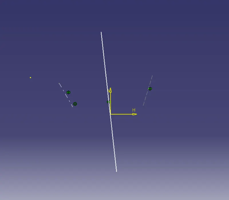
The base surface of the class-A was extracted to create a reference point on the surface using the point, create a line in the z-direction and an axis system was inserted to the point. Then using projection intersection along the yz plane is created and the two inclined lines were drawn inside the positioned sketch. Then bisecting lines with the two inclined lines were created.
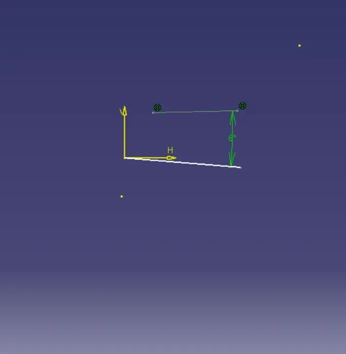
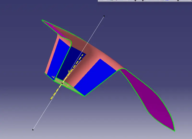
Now the same procedure is done along the xz plane but on xz plane, we only have one surface line so the center point is used to extrude a line along the z-direction and at an angle of 6 degrees from the surface line. Bisecting these two lines Sketch-1 and Sketch-2 the bisecting line is created and published as a tooling axis.
Creating Class-B Surface:
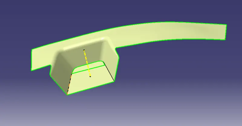
For creating the class-B surface the required surfaces like walls, rest surface, base have been extracted and then untrimmed. Then all the untrimmed surfaces is extrapolated to get intersections between them. Since the thickness of the Switch bezel is 2.5mm, the B-Surface is offset to 2.5 mm and the required trim operations must be carried out. Finally, the required corners have been filleted to 11.5mm(14mm-2.5mm) & 12.5mm (15mm-2.5mm). [ (15mm & 14mm) - fillet value of the A-surface, (2.5mm) – Thickness of the component ].
Creating Class- C Surface & Solid Body using Close Surface.
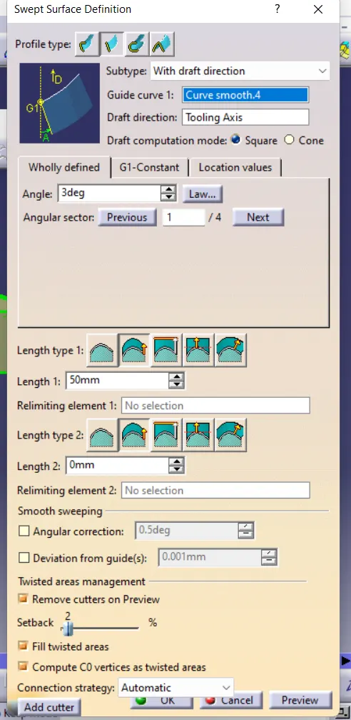
The edges of the Class-A surface are extracted using the boundary option and then converted into smooth curvature to avoid the patches. Sweep operation is performed selecting the smooth curves as the guide curve and tooling axis as the direction and draft angle as 3deg. Below is the required options selected for Sweep.
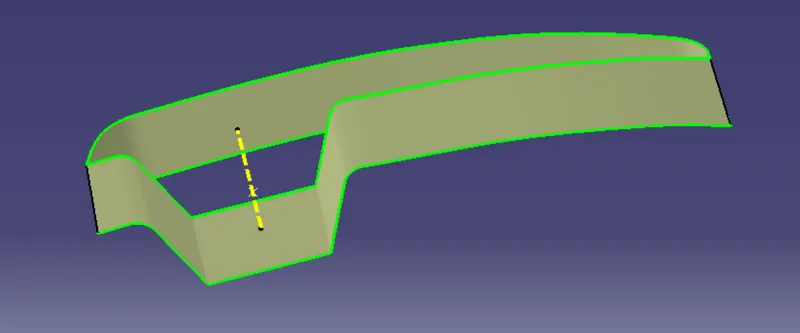
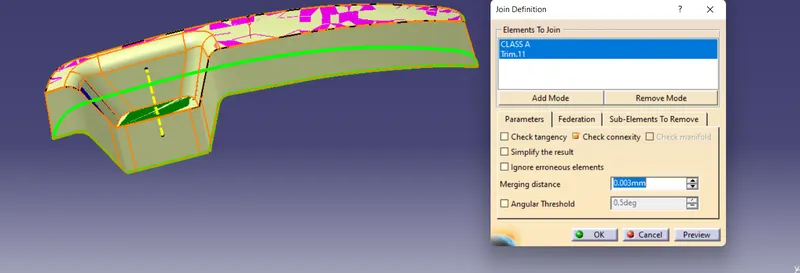
Join class-A and class-C surfaces. If there is any unnecessary boundary present, then increase the merging distance to not more than 0.003mm. and even after that if there is some unwanted boundary, extrapolate class-A by a small distance and trim it with class-C. Then trim the class-C surface with the class-B surface.
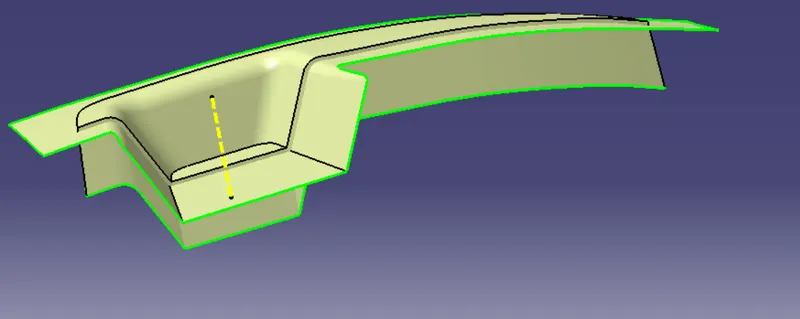
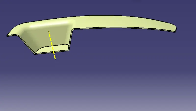
Select Boundary option & check whether there is any open boundary.
Go to Partbody Workbench & choose Close Surface feature. Select the final trimmed body of Class-A, Class-B & Class-C.
Press OK & Solid Body of Switch Bezel is obtained.
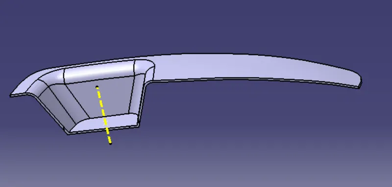
DRAFT ANALYSIS OF FINAL PLASTIC COMPONENT:
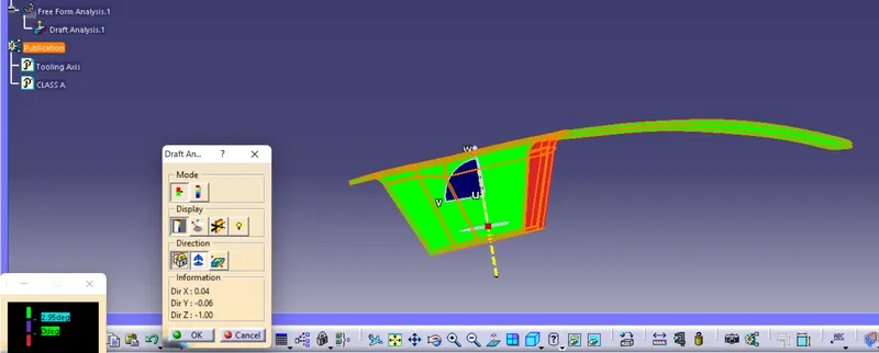
Change the view mode to custom view parameters & select Material mode, then choose the feature draft analysis from Insert. Select the compass from direction of dialouge box appeared & place it with the tooling axis by dragging the red pointer and then lock it. Then, by selecting the quick analysis mode, the nominal value will be 3 degrees and checked for the component's draft angle. The green colour area shows that it satisfies the 3-degree draft angle. If not satisfied, then by using the Running point tool the area is measured and then altered to get a successful draft for the created tooling direction(In this case we changed the angle to 2.95.)
Geometrical Tree Set
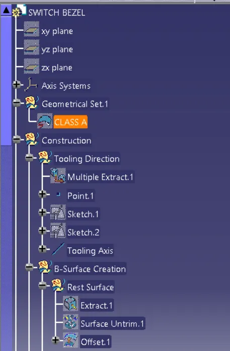
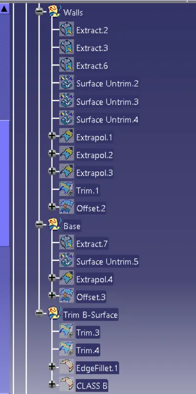
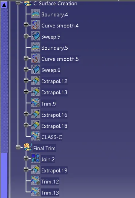
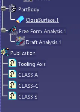
ISOMETRIC VIEW
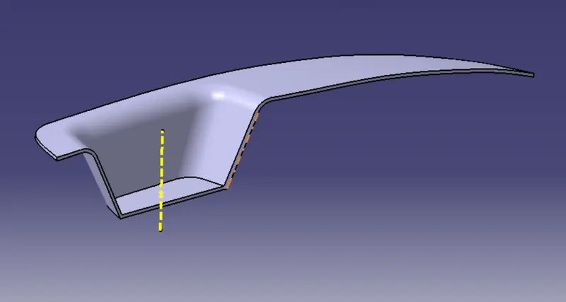
FRONT VIEW
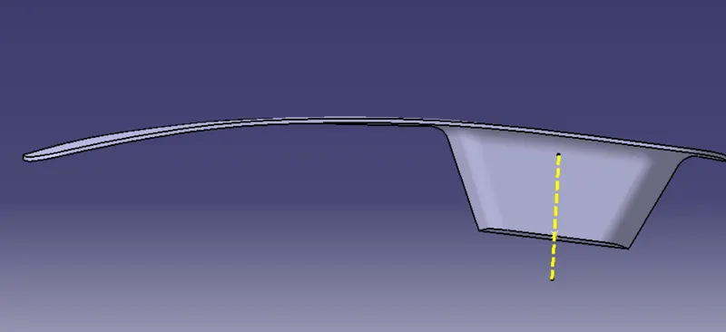
SIDE VIEW
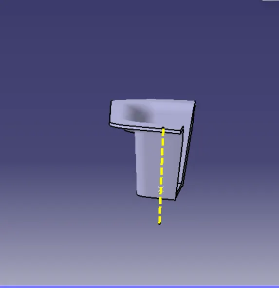
TOP VIEW
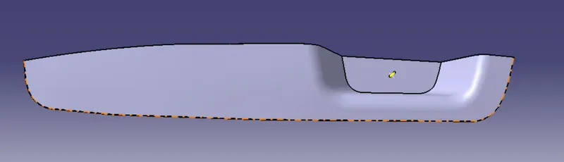
CONCLUSION
Switch Bezel plastic component using class-A surface successfully created and the draft analysis on final plastic component is performed.