Week 9 - Challenge 3 - Bumper
WORK REPORT
CLASS A SURFACE
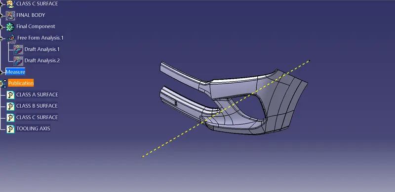
TOOLING AXIS
Tooling Axis is created at a point normal to the Class A surface and we give a line normal to it and if we take a normal to that line we should be able to see the entire body, tooling axis is a main component in the drawing because it is used to act as an axis in which the component moves in between the core and cavity when manufacturing, and draft analyis is done with respect to this tooling axis.
DRAFT ANALYSIS OF CLASS A
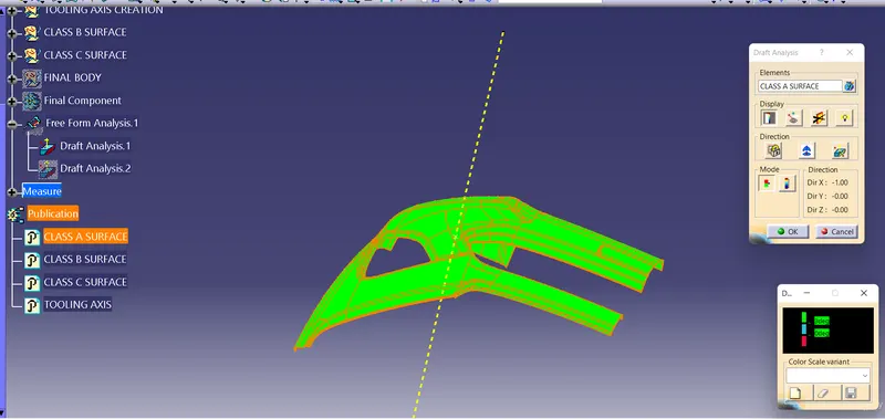
Draft analysis of Class A is done using a tooling axis and the body, it is done by keeping the body in material mode and after opening the analyis option we click on the axis to align it with our tooling axis and then the body is clicked to get diffent color code at diffrent area according to the color chart.
CLASS B SURFACE
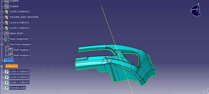
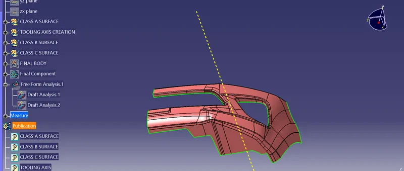
Class B surface is created by offsetting the class A surface to 3 mm(as specified) and the patches that are formed are covered using several method which involves extracting, extrapolating and trimming and the required parts are then joined with the main Class B surface.
CLASS C SURFACE
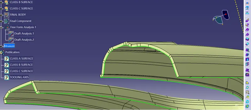
Class C surface are produced by using sweep function with the Class A surface using a boundary and producing a sweep using draft with reference to the Class A surface at 90 degree. Finally the Class B and combined Class C is trimmed together to get the final part, and the final part is created into a partbody using closed surface function
DRAFT ANALYSIS OF FINAL PART
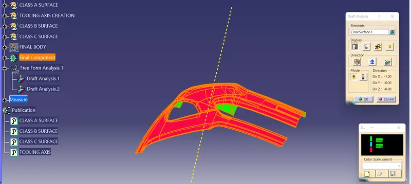
Here we get this color code because the top surface is at negative angle angle and the green surface is at 3 degree.
DIFFRENT VIEWS OF THE FINAL COMPONENT
TOP VIEW
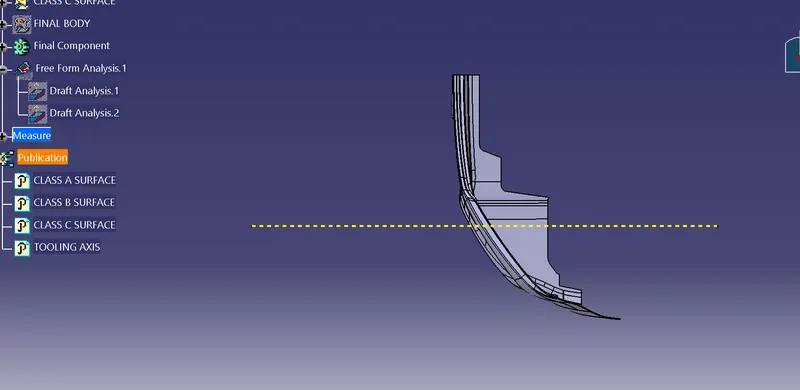
SIDE VIEW
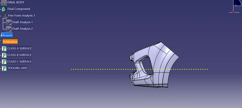
FRONT VIEW
ISOMETRIC VIEW