Week 8 - Challenge 1 - Base Bracket Design
REPORT ON BASE BRACKET
AIM - In this Challenge using Catia Software we design a Base Bracket from given Class A surface. It also includes the creation of Class-B & Class- C surface with a thickness of 2.5mm.
INTRODUCTION -
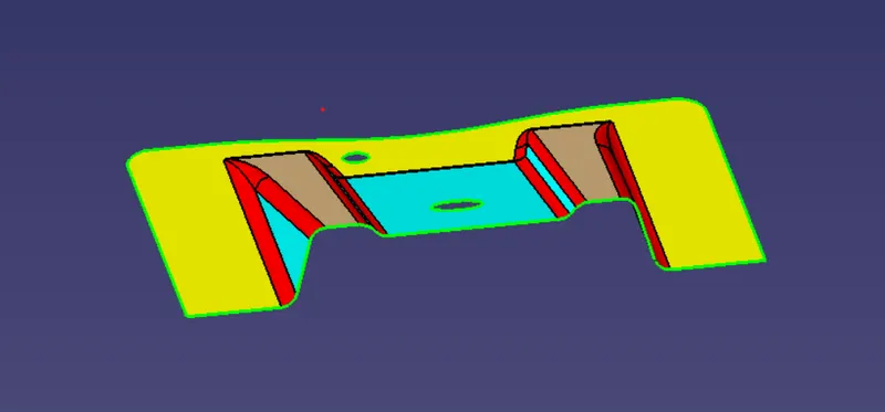
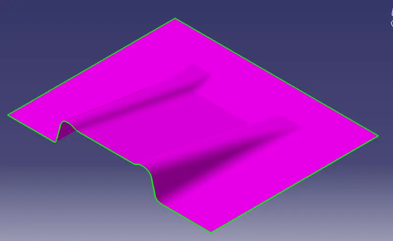
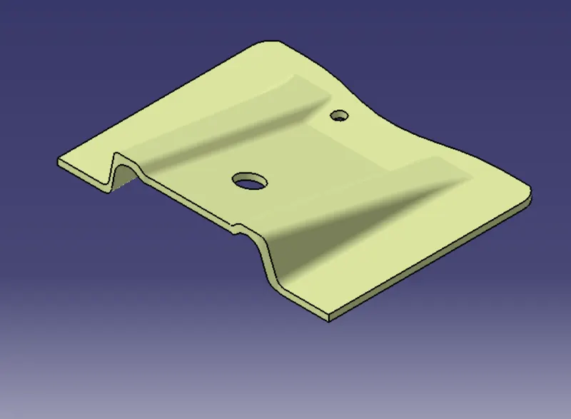
CLASS-A SURFACE: A surface made by the designer which is given as an input to the plastic modeler to work on. It is aesthetic surface and the outer most surface. Below shown is the given Class-A model of Base Bracket.
CONTENT
Creation Of Tooling Axis.
Analyse the Model carefully to see in which direction the tooling axis is more suitable. After careful analysis visually, since the surface has 2 holes that needs to be considered, it is better to set the tooling axis on z axis.
A dummy axis is made using point-direction(Orange Line), then by using intersection on YZ plane below lines are created.
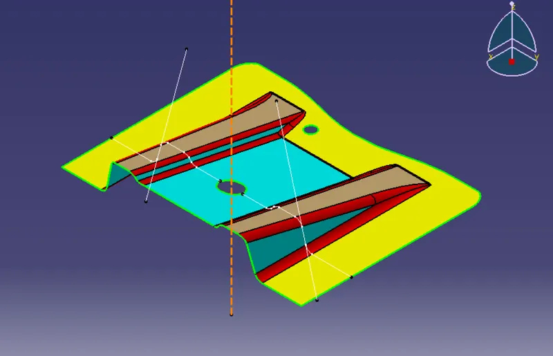
By using Bisecting option from Line Option we create tooling axis(Green line) in the Class- A surface.
Draft Analysis
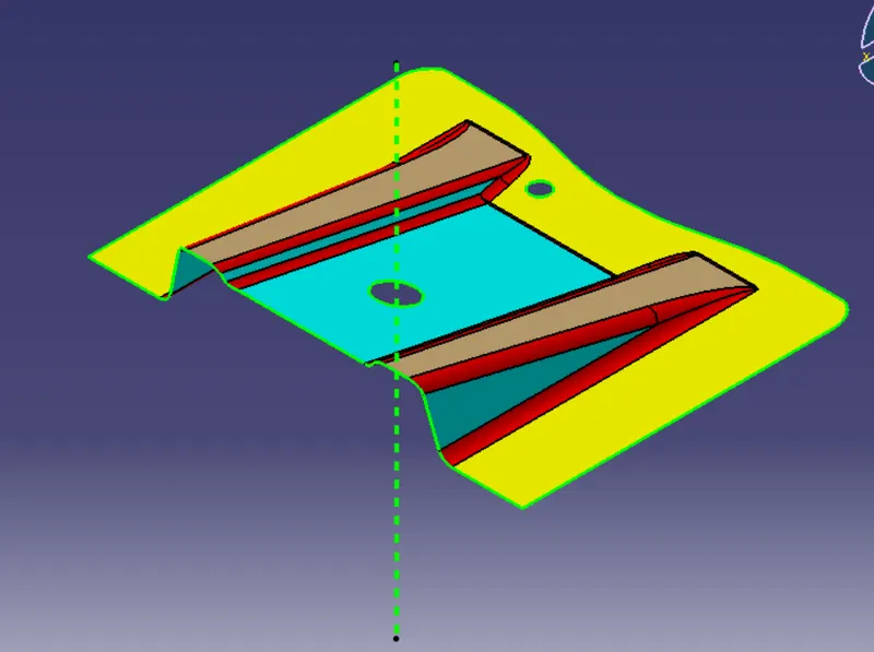
Go to insert-> analysis-> feature draft analysis. Align the tooling axis with the compass.
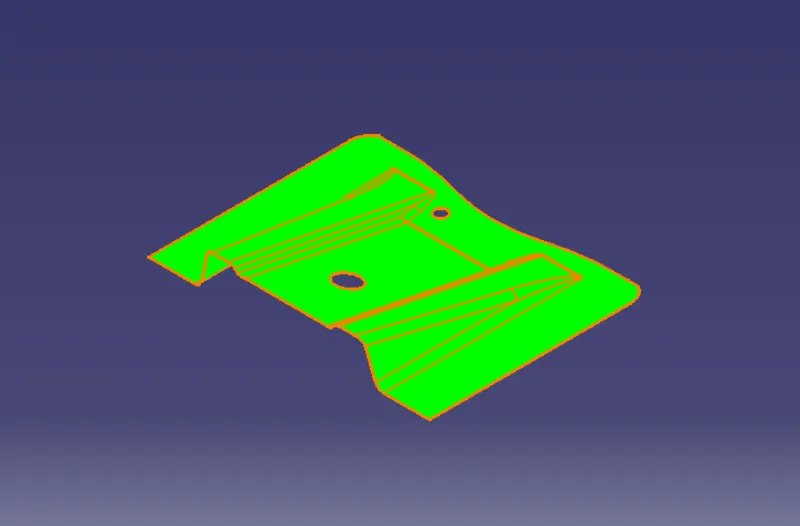
Click on the surface and see whether the surface is within the permissible limit of the draft values. The surface should be green and the analysis is done for 3degree draft. So as can be seen below, all the surfaces are more than 3deg.
CLASS-B Creation
For Class-B surface creation we extract surface from Class A and untrim them to obtain the original parent Class-B surface. These surfaces are then offset to the required thickness & extrapolated. After that, all the surfaces are trimmed into the required shape. Required fillets are given to the surfaces.
CLASS-C Creation
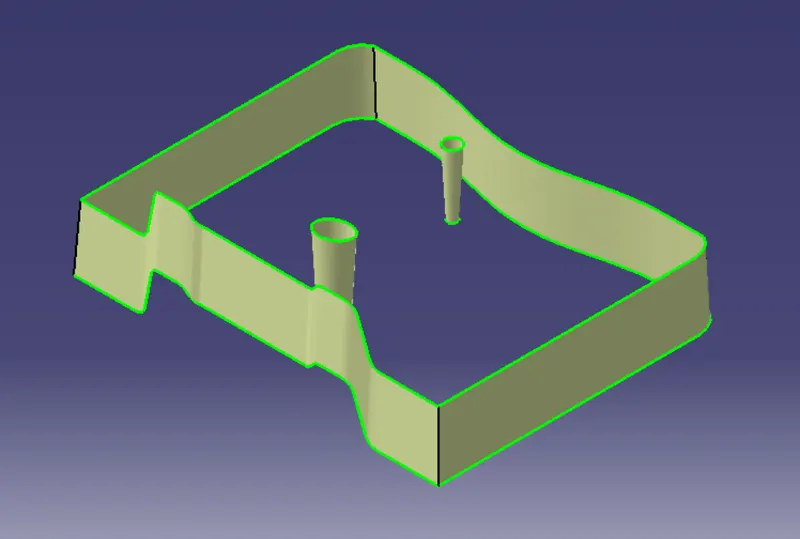
For creating this surface we have extracted the boundry of Class A using multi-extract and then converted to smooth curve. Now this smooth curve is swept along the draft direction with a 3deg draft.
Joining CLASS-A & CLASS- C:
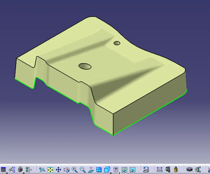
We use join option to create single body. This is done to make sure that the parting line doesn't lie between the these two surfaces & there is not any open boundry between class A and class C.
TRIM Class A + Class B + Class C:
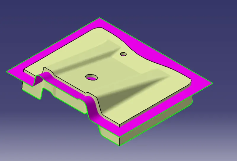
For this we have trimmed the above shown surface with the Class B surface using trim feature.
CONCLUSION
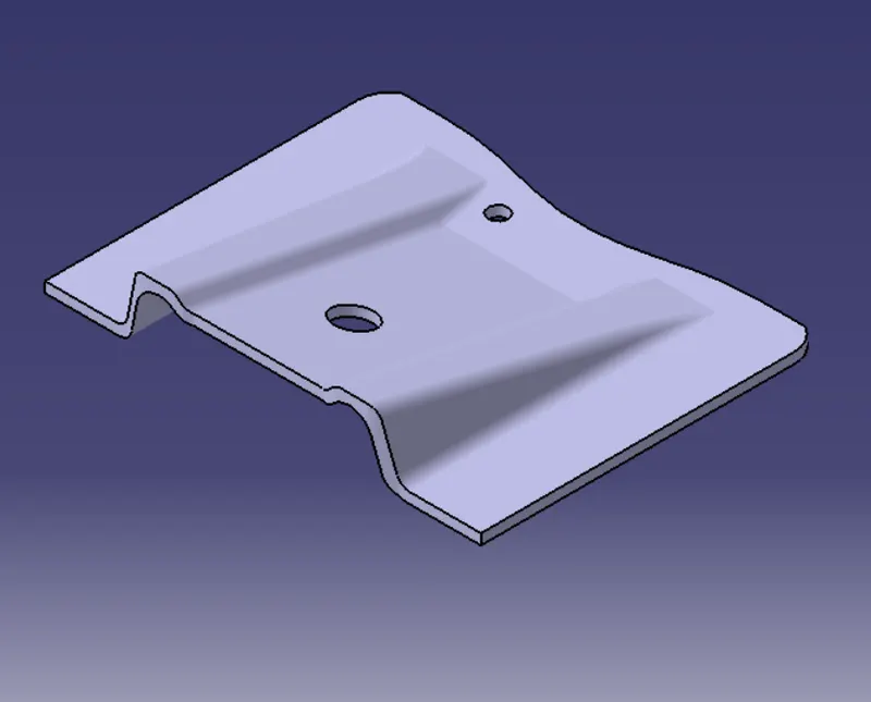
Define Part Body. Base Bracket as final product is created by using CLOSE SURFACE option. Choose Close Surface from Surface Based Featurre in Part Design & select the Final trim as object to close then press OK.
DRAFT ANALYSIS ON FINAL PRODUCT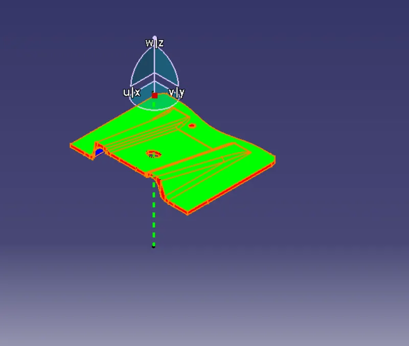
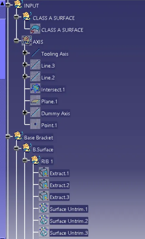
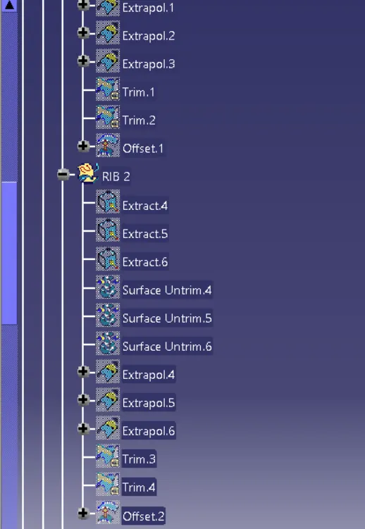
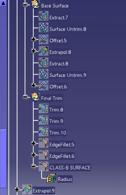
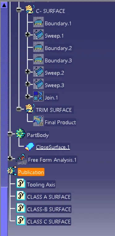
Geometrical Tree Structure