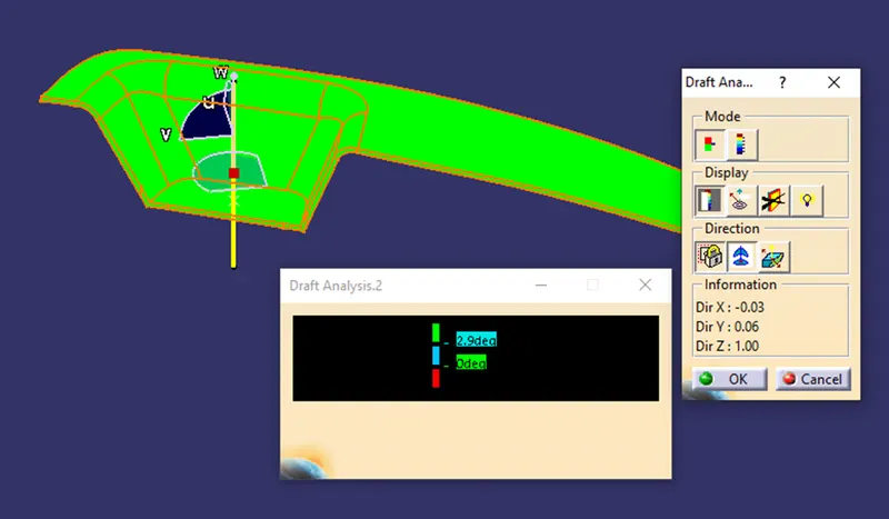
Week 8 - Challenge 2 - Switch Bezel Design
AIM – To create the tooling axis and do the draft analysis of the switch bezel.
INPUTS – 1. Class A Surface.
- The minimum Draft Angle Should be 3 degrees.
- The component thickness should be 2.5 mm.
TOOLING AXIS
- CREATION OF Y DIRECTION TOOLING AXIS
We have created the tooling axis in the y direction by the bisecting method
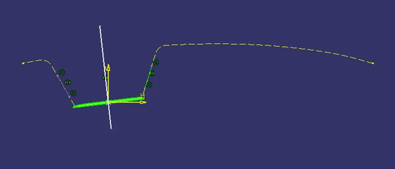
2. CREATION OF X DIRECTION TOOLING AXIS
Since we cannot extract the tooling axis here with bisecting method because only one edge is available, so we have created the tooling axis by assuming the draft angle of 4.8 degrees from the edge.
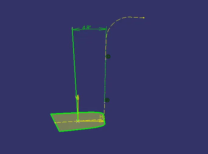
3. CREATION OF FINAL TOOL AXIS
By using the bisection of the two above tooling axis final tooling has been generated.
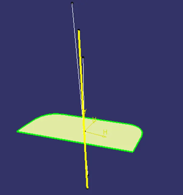
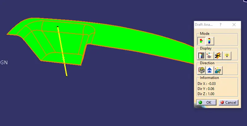
DRAFT ANALYSIS OF A CLASS SURFACE
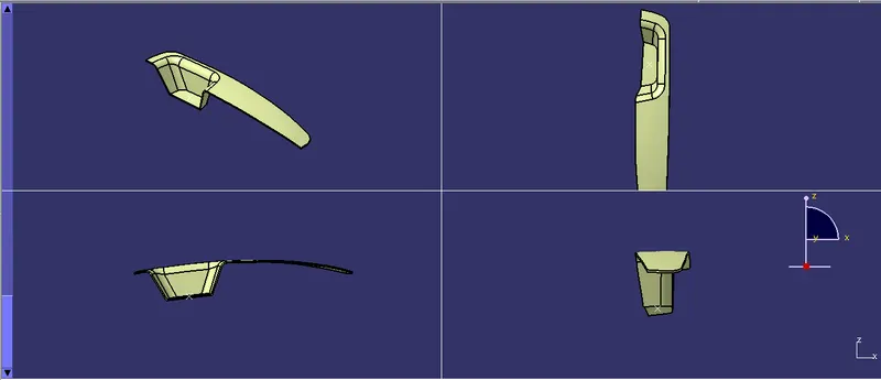
ALL THE VIEWS OF SWITCH BEZEL
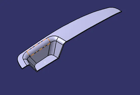
SOLID COMPONENT
DRAFT ANALYSIS OF FINAL COMPONENT