Week 8 - Challenge 2 - Switch Bezel Design
Q-1
ANS-1: Draft Analysis report for Class A surface
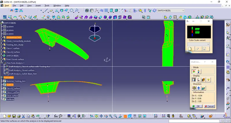
Draft Analysis report for Final plastic Switch Bezel component
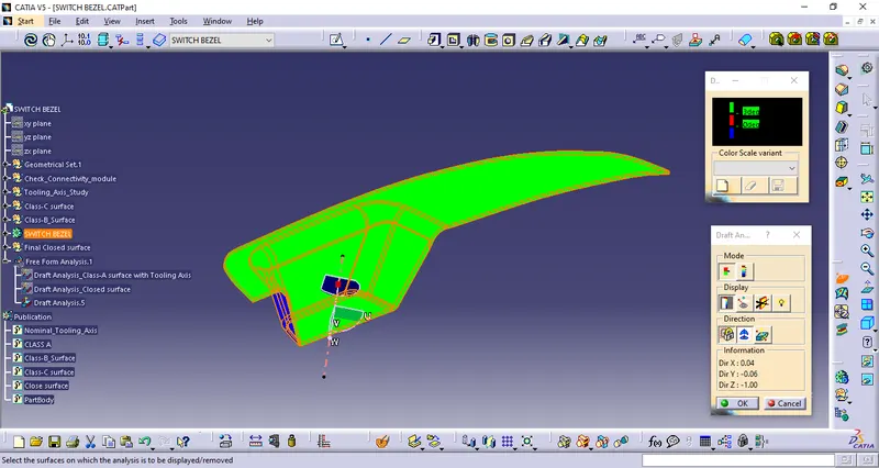
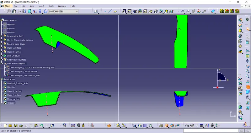
Draft Analysis_Procedure/Checklist
1. Connectivity of the surface model through,
join
Create boundary > Disassemble Sketch > Hide the surface > see the sketch for the result
2. If Connectivity is ok in Class-A surface
3. Decide tooling axis
See the component in the XY plane, YZ plane, and XZ plane
In the XY plane - Check the cavity and core movement whether it will make the component or not in that direction
The same to be carried for all directions list the Ok or Ok not possibilities if ok list the process for selecting a cost-efficient method
4. Need to draw the Tooling axis
5. Draft analysis
Direction to sink with the tooling axis of the component
For Draft analysis checking component should be in material mode
Check that component has less than a 3deg angle in the surface of the component
Creation of Tooling Axis for the Class-A Surface,
- Take a look at Class-A surface through various plane views
- Need to check the feasibility of the component for the direction of manufacturing the component
- Decide the views which represent the axial direction of the component to manufacture
- If multiple views can show the results to manufacture at that time create a list of manufacturing methods
- Eliminate the methods which involve the Costly manufacture of component
- In the finalized view, create a point in the surface parallel to the plane of view
- Create a coordinate system through the point
- Create the intersection sketch of the class-A surface through a perpendicular plane of views from the direction of view
- In the profile observe the sketch which along with the selected axis for the tooling axis
- Extend the sketch and check the angle between those lines
- Draw the Bi-secting line between the surface using the Bi-secting line creation command
- Take another perpendicular view of the class-A surface
- Create the intersection of the class-A surface
- Check the sketch in that profile which is along the selected axis
- If it is draw the line over the sketch to check the angularity of the sketch with the direction
- After the Creation of two lines from the two perpendicular views
- Draw the bisecting line among those two lines which represents the final Tooling axis for the Class-A surface