Week 8 - Challenge 2 - Switch Bezel Design
AIM:
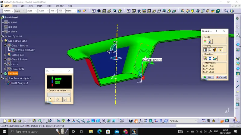
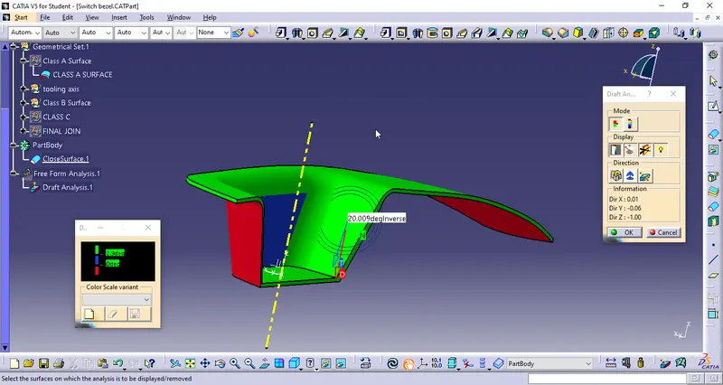
To create a Switch Bezel plastic component by closed method with reference to the class A surface and do the draft analysis for the component.
Steps followed
1. The class A surface is checked for the connectivity of the surface and ensure it is completely joined and there will be no gap between the surfaces.
2. If it is not join together make it with a minimum tolerance of 0.001 to 0.003 and check for connectivity of the surface.
3. Connectivity of the surface can be done by two ways by join method and by boundary method.
4. Split the surfaces into multiple profiles then Identify the surface where it is not possible to create a tooling axis and check on which direction is best fit for tooling axis and then define the tooling axis and draft direction.
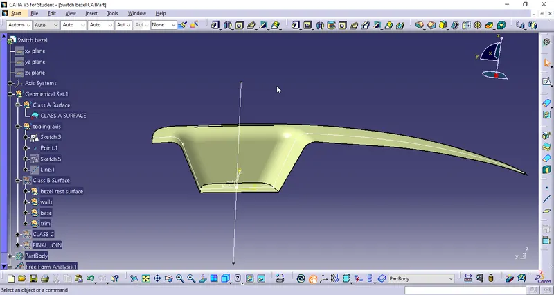
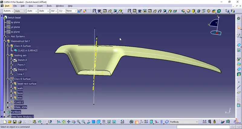
5. Here for defining the tooling axis first we have created a point at middle of the base surface and create an axis with respect to that point then define the tooling axis using the intersect method by creating a bisecting line.
6. Then do a draft analysis on the class A surface and identify the draft angle then give the nominal value for the draft.
CREATING TOOLING AXIS:
The direction in which the mould open and closes is called the tooling axis direction.
Check the connectivity of the surface and ensure there will be no gap between the surfaces and then define the tooling axis.
It is nothing but the direction in which the mold opens and closes the draft angle needed to be provided by considering this tooling axis.
We can create a tooling axis by using the bisecting method.
CREATING B SURFACE:
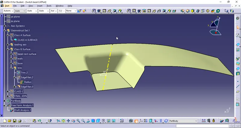
B surface is created by extracting the walls and sides of class A. Class B surface is further divided into three parts which are BEZEL REST SURFACE, BASE, WALLS and TRIMS, all these surface can be made by extracting the surfce form calss A surface and then untriming it by using untrim command and the extrapolating the surface if required. After getting the surface trim the unwanted area using trim command, make sure to choose right direction while trimming the surface. Offset the final surface according to the required or given thickness for the component.
Class B surface is further divided into three parts which are BASE, WALLS and TOP WALLS, all these surface can be made by extracting the surfce form calss A surface and then untriming it by using untrim command and the extrapolating the surface if required. After getting the surface trim the unwanted area using trim command, make sure to choose right direction while rtrimming the surface. Offset the final surface according to the required or given thickness for the component.
CREATING C SURFACE:
C surface is created between the class A and class B surface to close the open boundary. It is created from the boundary lines of class A surface and by extracting the supporting surfaces then sweep the boundary lines with reference to the extracted surfaces.
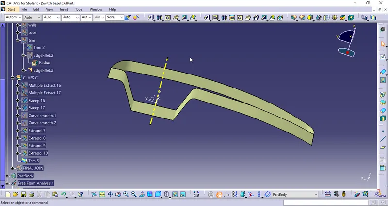
In order to create C surface we need to first create or extract the boundary of class A surface and then create a surface using sweep command, the generated surface should be greater then the required thickness of the component.
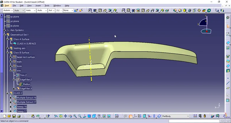
Then join the class A surface and C surfaces together by join command then check it for connectivity of the surfaces if it is ok then finally trimmed it with B surface we will get the final component again check whether the final body is closed by using boundary command.
Closed solid body is created by using the close surface on part workbench by selecting the final Trimmed component and do the draft analysis for the same.
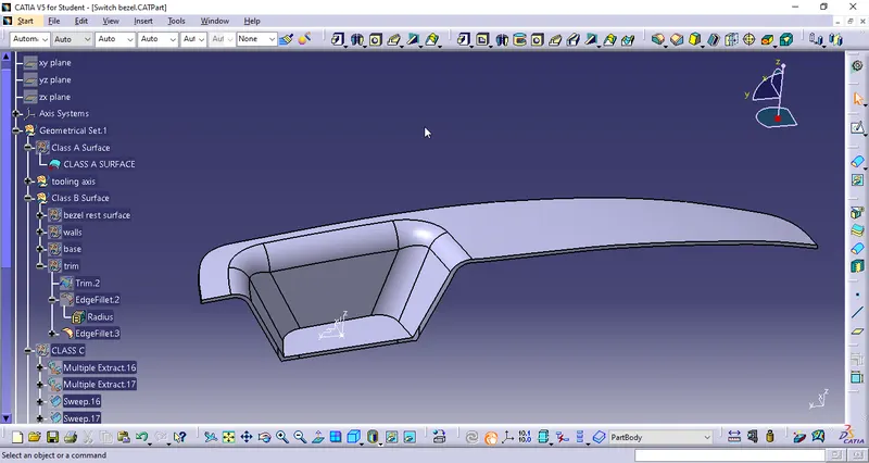
DRAFT ANNALYSIS: