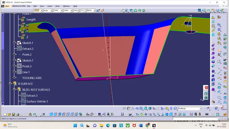
Week 8 - Challenge 2 - Switch Bezel Design
The Draft analysis report the given Class-A surface
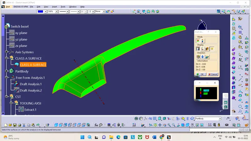
The Draft analysis report for final product
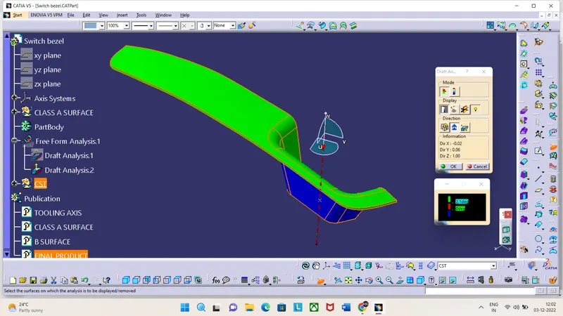
ISOMETRIC VIEW
FRONT VIEW
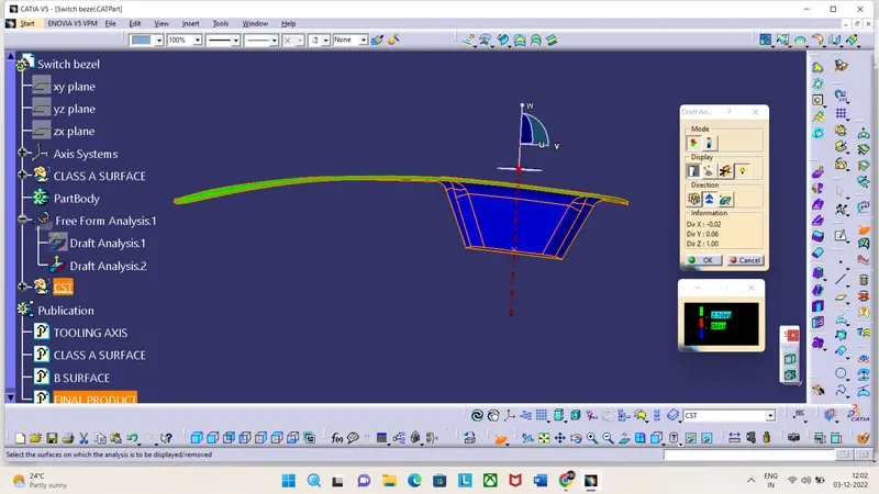
SIDE VIEW
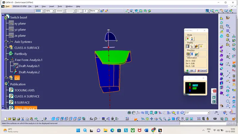
TOP VIEW
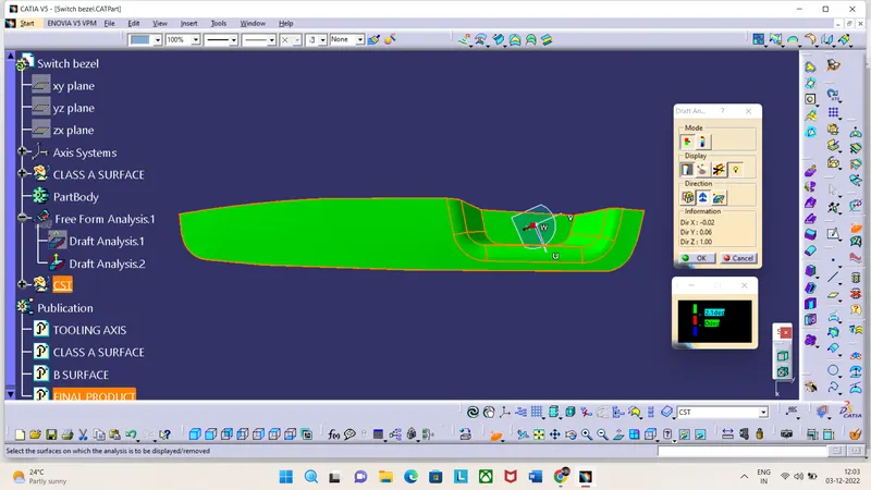
The draft analysis
The steps to follow for draft analysis are:
Select the draft analysis.
Select the quick analysis mode.
Select the compass to the tooling axis.
After that click anywhere on the Class A surface.
A window popup and we can observe there 3 different color variations which means that we have given a draft angle of 3 degree
The green color represents the draft is more than three degrees.
The blue color represents the draft is between 0 and 3 degrees.
The red color represents whether the draft is negative or less than three.
Screenshots for the explanation of draft analysis of class A surface
Tooling axis creation-
Creating the tooling axis by using bisecting line and a dummy axis.
The steps to follow for creating a tooling axis:
Open the file which contains the Class A surface, after creating a geometrical set "Tooling Axis" then select the most appropriate position which can clear the part in one short for manufacturing.For the given component i have created two dummy axis ,one in x-axis and the other one in y-axis.
In x-axis i have created two lines with respect to the walls of the class A surface.As shown in the screen shot.
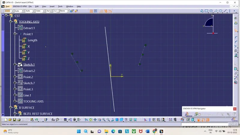
In y-axis i have created two points on the class A surface and joined both using line and drawn line opposite to the other line at an angle of 3 degree.
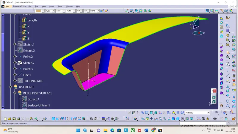
The Last step create a bisecting line using the above 2 lines and named it as Tooling axis after that hide the dummy tooling axis