Week 8 - Challenge 1 - Base Bracket Design
Draft analysis report for Class-A surface
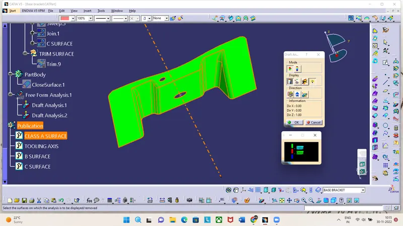
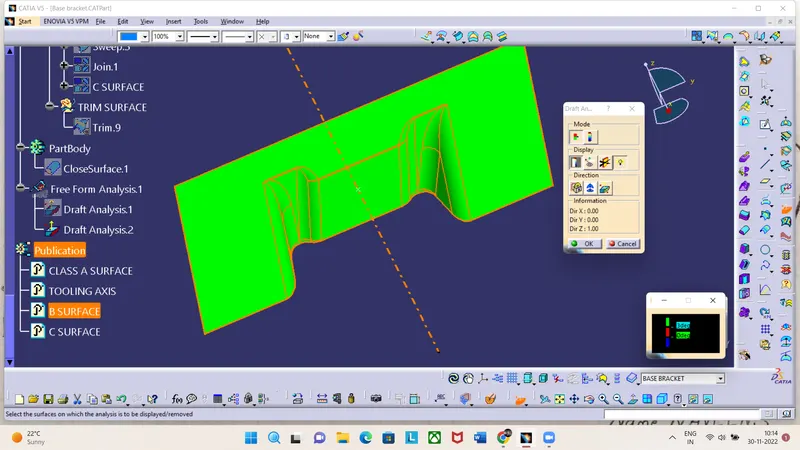
Draft analysis report for B surface
Draft analysis report for Final Plastic Component
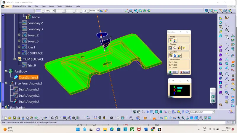
ISOMETRIC VIEW
FRONT VIEW

SIDE VIEW
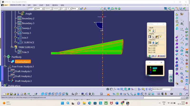
TOP VIEW
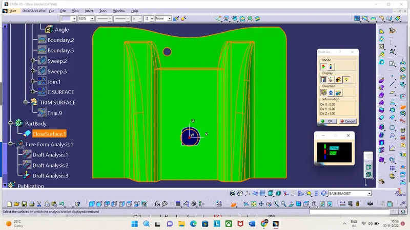
The draft analysis and the tooling axis creation.
The steps to follow for draft analysis are:
Select the draft analysis.
Select the quick analysis mode.
Select the compass to the tooling axis.
After that click anywhere on the Class A surface.
A window popup and we can observe there 3 different color variations which means that we have given a draft angle of 3 degree
The green color represents the draft is more than three degrees.
The blue color represents the draft is between 0 and 3 degrees.
The red color represents whether the draft is negative or less than three.
Screenshots for the explanation of draft analysis of class A surface
Tooling axis creation-
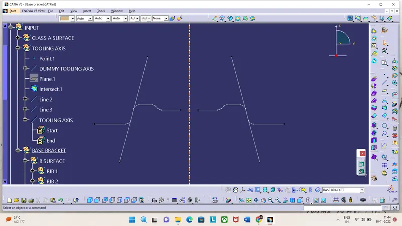
Creating the tooling axis by using bisecting line and a dummy axis.
The steps to follow for creating a tooling axis:
1. Open the file which contains the Class A surface, after creating a geometrical set "Tooling Axis" then select the most appropriate position which can clear the part in one short for manufacturing.For the given component i will select hole
center.
2. Then create a point in the center of the hole selected then draw a dummy line on the z-axis.
3. After that create a plane on the point created with reference to YZ plane direction.
4. Then select the intersect tool that gives the intersection on the Class A surface.
5. Now create 2 lines using the point and point method and extrude the line both sides were well.
6. The Last step create a bisecting line using the above 2 lines and named it as Tooling axis after that hide the dummy tooling axis