Week 8 - Challenge 2 - Switch Bezel Design
Aim - This project aims to create a switch bezel plastic component using the given class A surface following the OEM standard. and perform the draft analysis.
Objective:
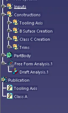
- Ensure Proper Tree Structure.
- Geometrical sets should have a proper name based on the sketches present inside them.
- All the sketches should be created under the Geometrical set.
- Use the Close Surface feature to make a solid body from the surface.
- To publish the Tooling Axis, Class A.
Design methodology:
- Insert the class A surface of the switch bezel in CATIA software.
- Determining the tooling axis for the switch bezel
- Creation of class B surface.
- Creation of class C surface.
- Join the switch bezel's class A, class B, and class c surfaces and ensure all the surfaces are closed surfaces.
- Use the Close Surface feature to make a solid body from the surface.
- Finally, Perform the Draft analysis on the switch bezel final plastic component.
1.Tooling Axis - Generally 3 methods used to create the tooling axis.
- Normal to plane (Large surface avilable).
- Bisecting the line.
- Point and Direction.
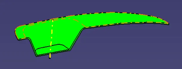
For switch bazel Normal to plane (surface ) is used for tooling axis as Class A surface clears in draft analysis.
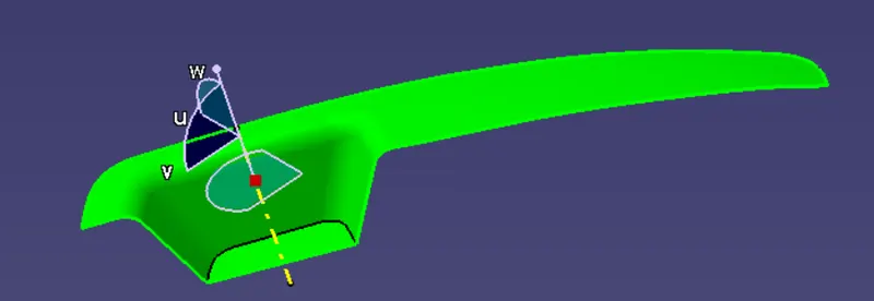
2. Creation of B surface - Divided the class-A surface into 3 different surfaces as shown below.
- Bezel rest surface
- Base
- Side walls
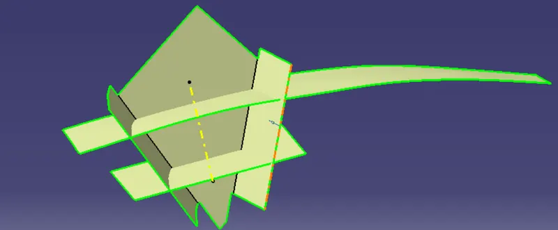
After Trims Class B surface.
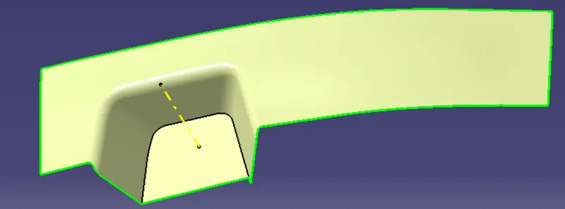
3. Creation of C Surface -The edges of the Class-A surface are extracted using the multiple extracts and then converted into smooth curvature to avoid the patches.Sweep operation is performed (with draft direction) selecting the smooth curves as the guide curve and tooling axis as the direction and draft angle as 3deg.
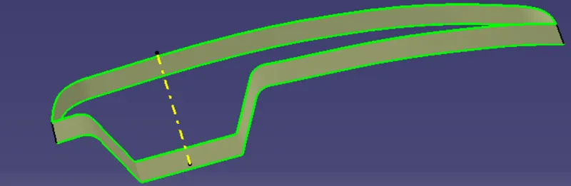
4.Final Trims-
4.1.Class A+ Class C - Make sure that there is no unnecessary boundary present, if there is then increase the merging distance to not more than 0.003mm. and even after there is some unwanted boundary, extrapolate class-A by a small distance and trim it with class-c instead of joining them.
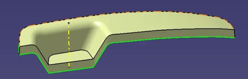
4.2.Class A + Class C + Class C - Then trim the class-C surface with the class-B surface.
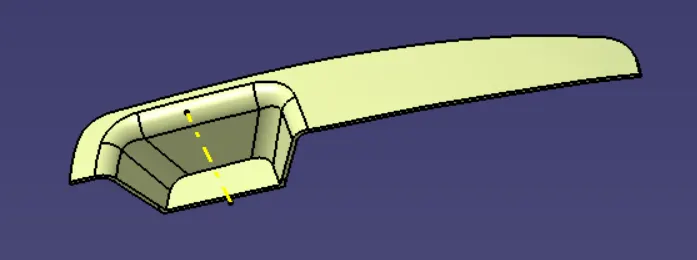
5.Switch Bezel Final Component -
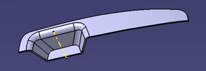
6.Draft Analysis - Draft Analysis is used to check the whether the minimum draft of 3deg is maintained or not.The draft analysis command enables you to detect if the part you drafted will be easily removed. This type of analysis is performed based on color ranges identifying zones on the analyzed element where the deviation from the draft direction at any point, corresponds to specified values.
Tree Structure -