Week 8 - Challenge 2 - Switch Bezel Design
AIM:--
Create the Switch Bezel Plastic component through the given Class-A surface. To begin with, the tooling axis for the given Class-A Surface should be created meeting the requirements of the draft angle and at the end perform the Draft analysis on the model.
Take the Thickness of the component to be 2.5 mm
To be able to create solid from the given Class-A surface, by considering tooling axis and draft analysis.
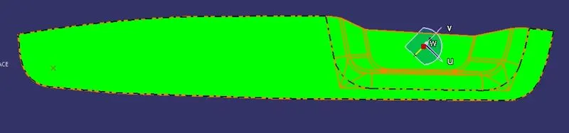
- The given Class-A surface:--
WHAT IS CLASS A SURFACE ?
It is an Asthetic surface and which is visible to the customers ie, Top surface,
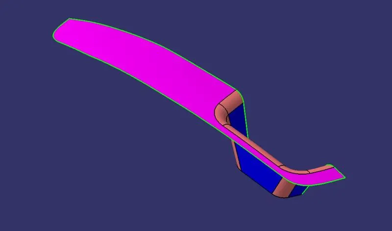
The base wall is extraced and A point was created at the center of the base wall , Using that axis system is inserted,
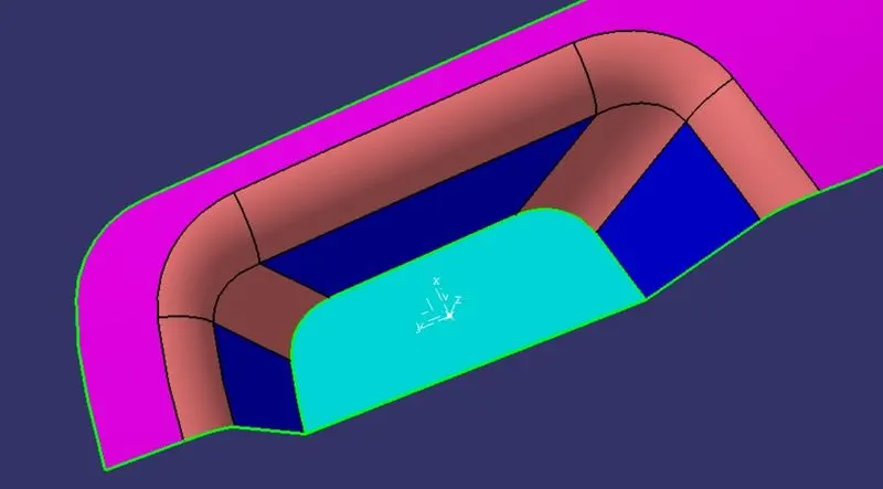
- Tooling Axis:--
~ The tooling axis is the tool movement axis (core/cavity).
~ This axis will decide the draft direction.
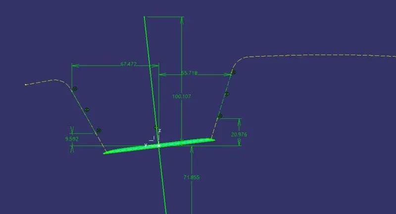
FIG:--create an intersection along yz plane and create an bisecting line.
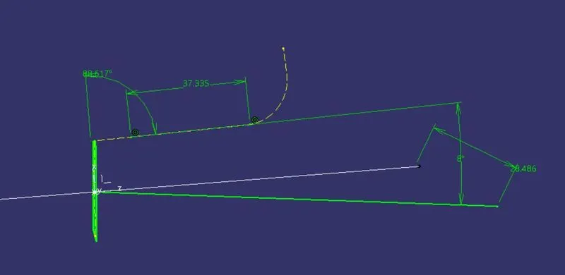
FIG:-- create an intersection line using xz plane and create a line which is 7-8deg apart.
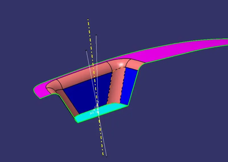
FIG:--Now create a bisecting line from the sketch1 line and from the sketch 2 line.
Tooling axis is ready,
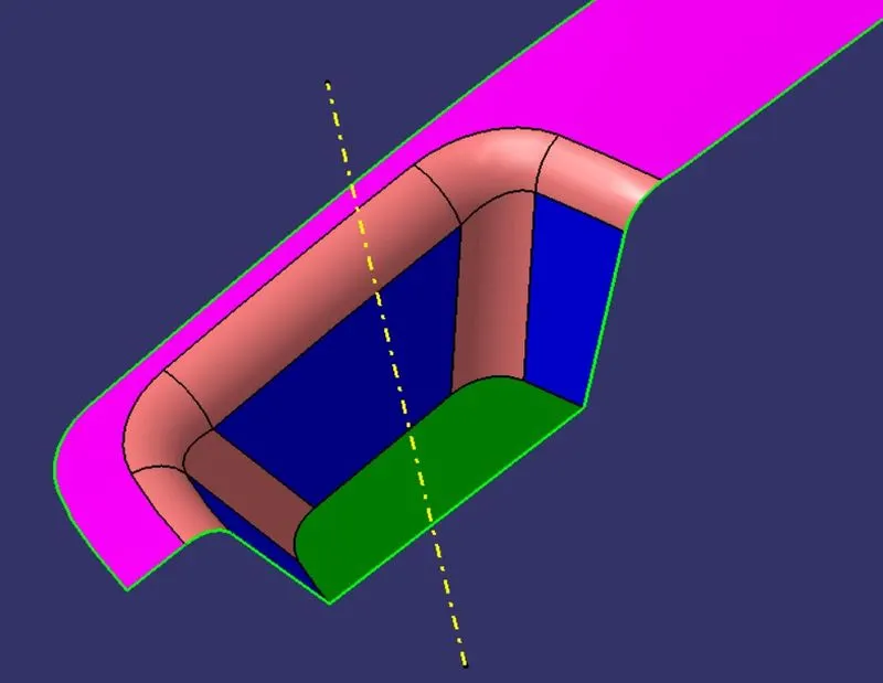
- Performing draft analysis on the given Class A Surface:--
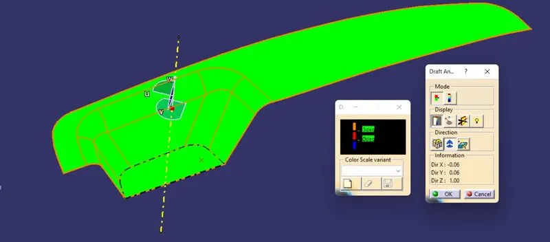
FIG:--The above picture is the result of the draft analysis.
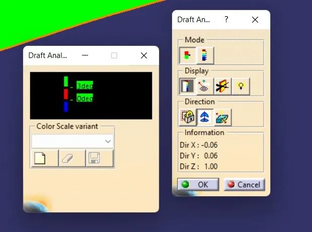
FIG:--The draft is considered as 3 degrees.
- THE CTREATION OF CLASS B SURFACE :--
WHAT IS CLASS B SURFACE ?
The surface which is thicken and applying the engineering features in it that sorface is called as CLASS B SURFACE
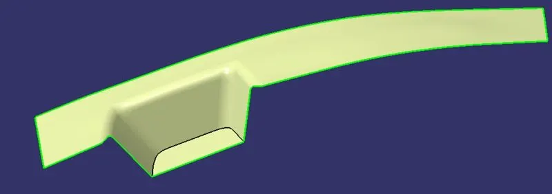
FIG:--By extracting the surfaces from class A and then offsetting the extracted surface we got a Class B surface that is 2.5mm below class A.
- THE CREATION OF CLASS C SURFACE:--
WHAT IS CLASS C SURFACE ?
The surface which joins the class A and B together that surface is called as CLASS C SURFACE .
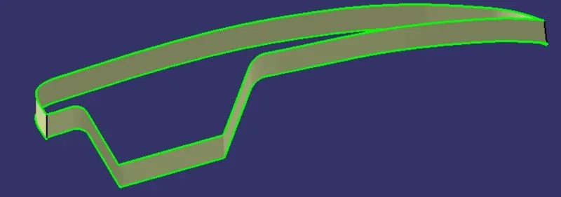
By using the MULTIPLE EXTRACT Command create a boundary and use SMOOTH CURVE Option to smoothe the curve and use Sweep command to create a surface along the tooling direction.
And the angle of draft given in Sweep is 3 Degrees.
- NOW JOINING ALL THE THREE SURFACES :--
TRIM SURFACE A WITH SURFACE C :--
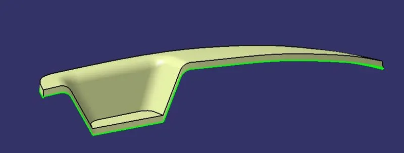
TRIM SURFACE AC WITH THE SURFACE B:--
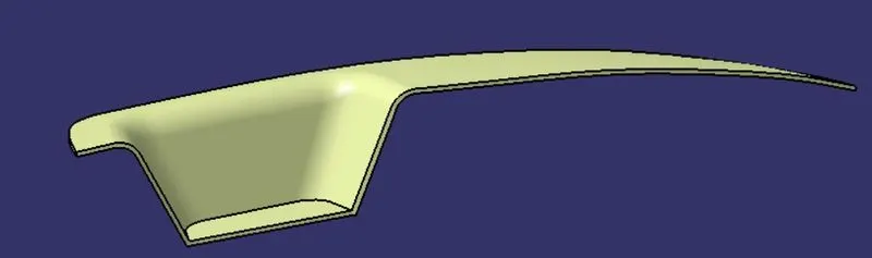
- NOW CREATING THE CLOSED SURFACE :--
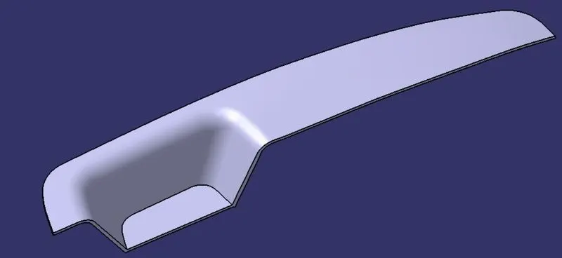
FIG:--The Solid is made by using the Close surface tool.
- PERFORMING DRAFT ANALYSIS FOR THE WHOLE BLOCK:--
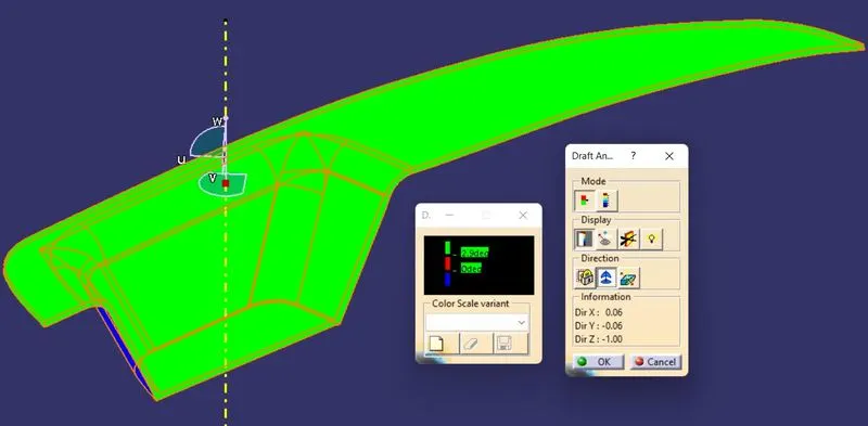
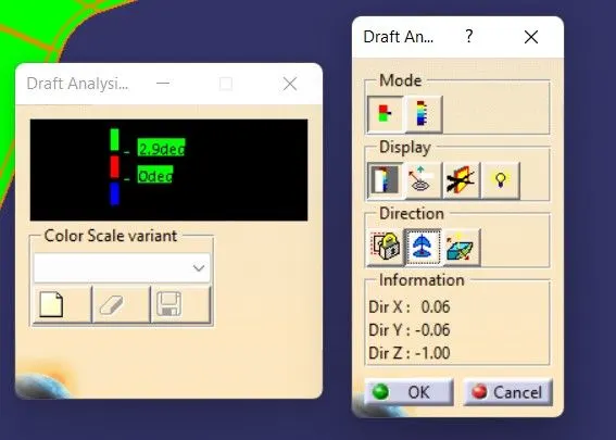
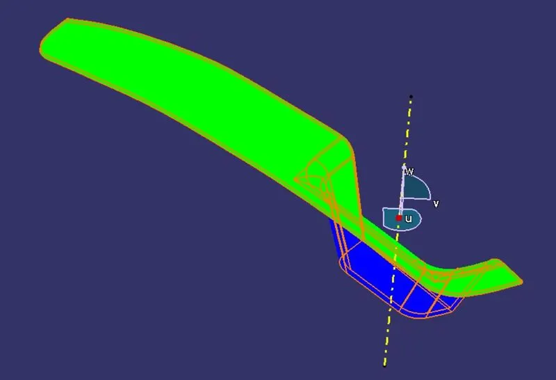
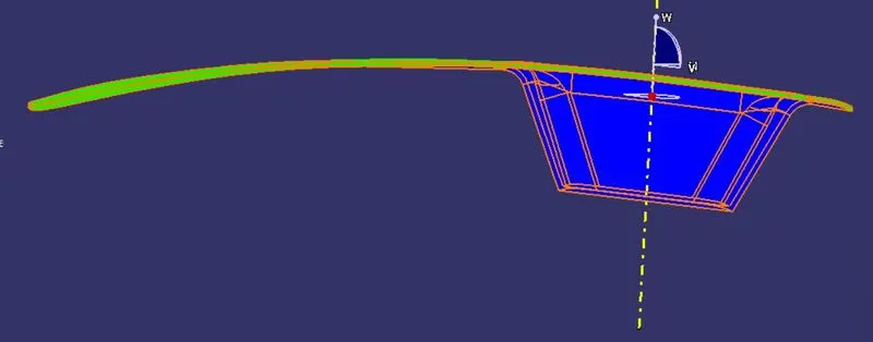
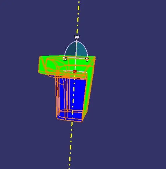
Performed the draft analysis anf it had cleared the draft analysis for 2.9degrees.
- Images of the color scale variant
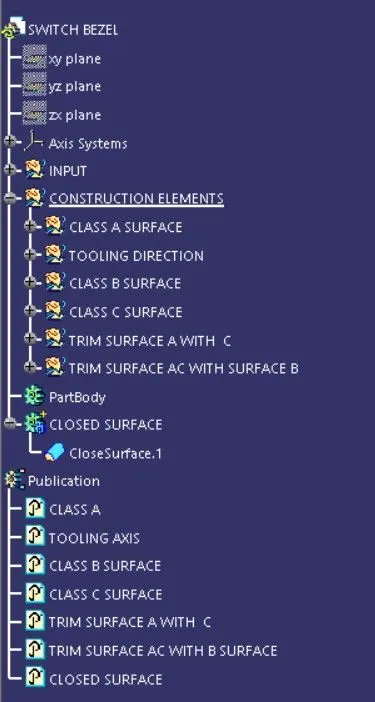
- TREE STURCTURE:--
- Screenshots of the solid model with the proper color code of the draft angle in various orientations (Isometric, Front, Side, and Top View)
ISOMETRIC VIEW:--
FRONT VIEW:--
SIDE VIEW:--
TOP VIEW:--