Week 8 - Challenge 2 - Switch Bezel Design
Week 8 - Challenge 2 - Switch Bezel Design
AIM :- To create the Switch Bezel plastic component through the given class A surface and create the required Tooling axis and perform the Draft analysis on the model.
INTRODUTION
The control panel bezel is the frame part of the window switch that holds its switch covers and buttons into place. Moulding is the method used to manufacture the plastic trims of an automotive by most OEM’s, hence by considering the manufacturing consideration the switch bezel is designed.
DRAFT ANALYSIS
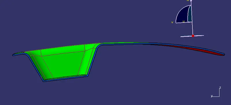
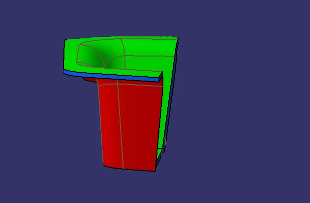
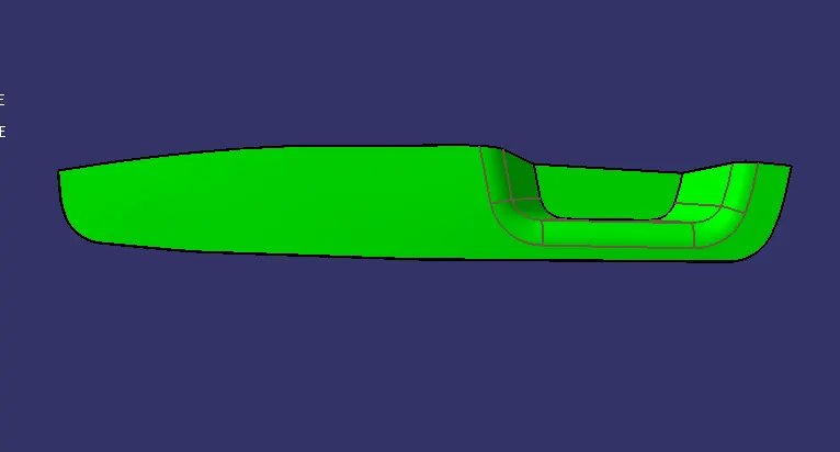
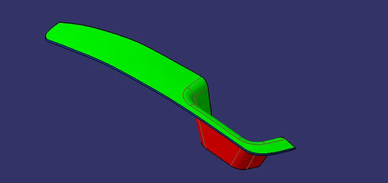
The Draft Analysis command enables you to detect if the part you drafted will be easily removed. This type of analysis is performed based on color ranges identifying zones on the analyzed element where the deviation from the draft direction at any point, corresponds to specified values.
Drafts are defined on molded parts to make them easier to remove from molds. There are two ways of determining the objects to draft: either by explicitly selecting the object or by selecting the neutral element, which makes the application detect the appropriate faces to use.
- First the class – A surface is checked before creating the Class – B&C surface and finally the solid body must be analysed. Both can be done by following the below procedures.
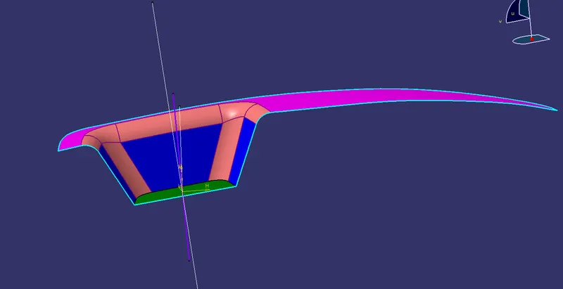
- By changing the view mode to custom view parameters – Material mode then the feature draft analysis is enabled.
- Then the compass was activated and placed with the tooling axis by dragging the red pointer and then locked it.
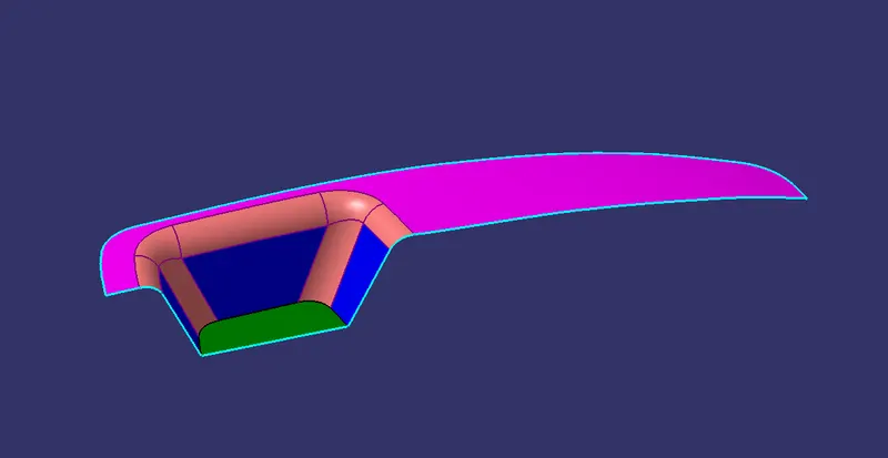
- Then, by selecting the quick analysis mode, the nominal value will be 3 degrees and checked for the component's draft angle.
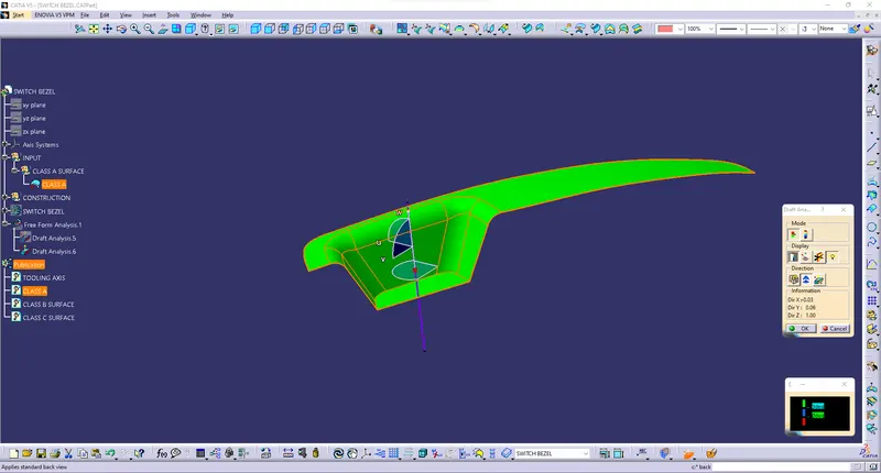
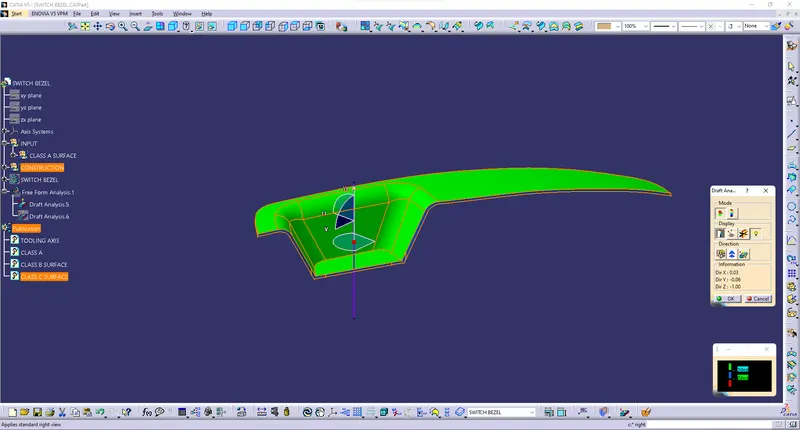
- The green colour area shows that it satisfies the 3-degree draft angle. If not satisfied then by using the Running point tool the area is measured and then altered to get a successful draft for the created tooling direction.
DRAFT ANALYSIS FOR CLASS A SURFACE
DRAFT ANALYSIS FOR FINAL COMPONENT
CREATION OF TOOLING AXIS
- Considering the Ejection from the cavity of the mould after manufacturing the interior trim (switch bezel) must have the nominal 3-degree draft angle.
- Hence the tooling direction is created by considering the above factor and bisecting method is used.
- The base surface of the class – A was extracted and a point at the centre is created and an axis system was inserted to the point with the current feature is disabled.
- Then, using project intersection along yz plane is created and the two inclined lines were drawn inside the positioned sketch. Then bisecting lines with the two inclined lines were drawn.
- Now the same procedure is done along the xz plane but on one side we don’t have inclined lines so the centre point is used to extrude a line along the z-direction and gave a measurement of 5 degrees (Tentatively).
- With these two lines from sketches 1 and 2, the bisecting line is crated and published as Tooling Axis(tooling direction).
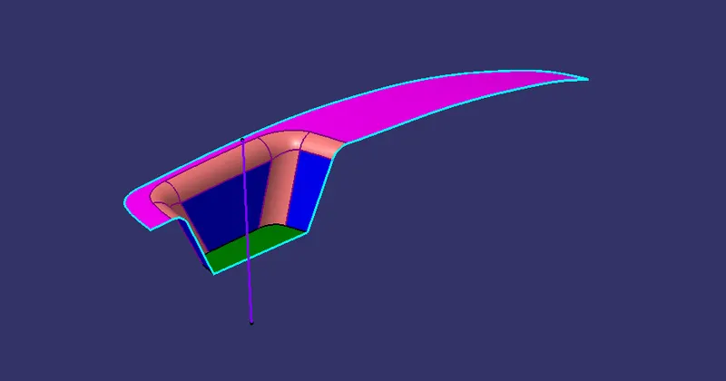
BISECTING METHOD:
There are several ways to create a tooling axis, one of the methods is the Bisection method, where the line is created by bisecting the other lines and the point.
In the above picture the tooling axis is created by using bisecting method.
Step1:
The intersection is crated directly in a sketch by using intersection option, were created by simply using intersection tool
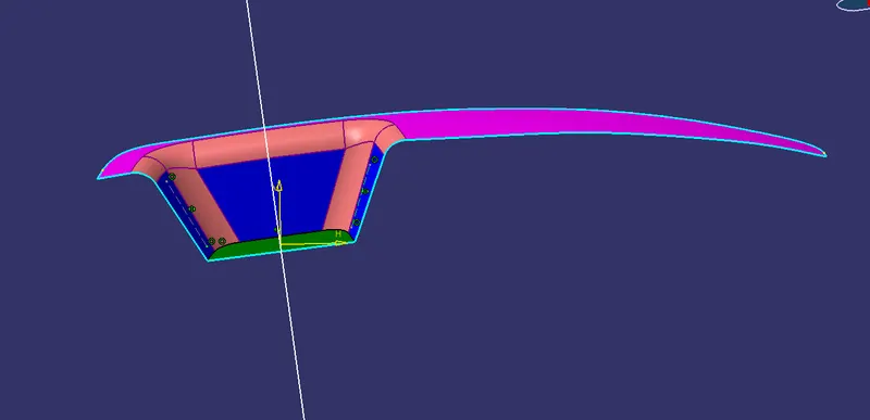
Step 2:
The lines are drawn by taking the intersection lines are references. Just make sure to select the two points as a line type.
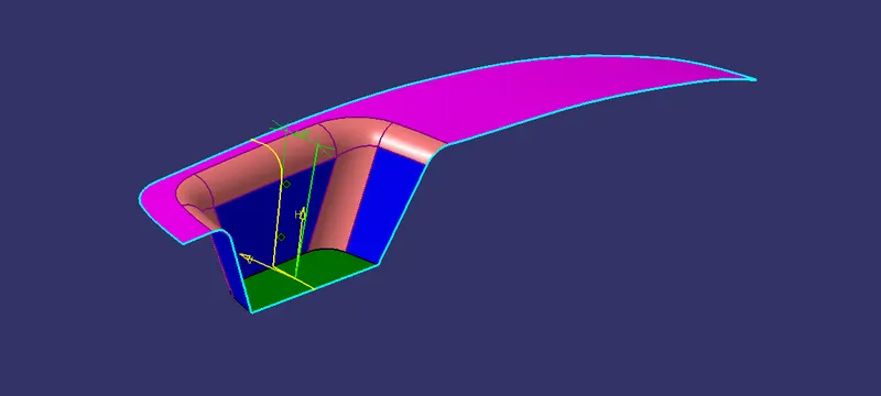
Step 3:
The two lines were drawn by simply selecting the two points.
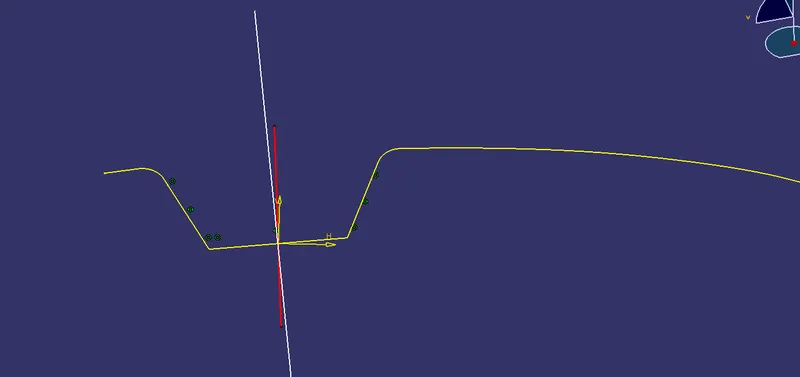
Step 4:
The tooling axis is created by using the line tool, just make sure that to select the bisection option as a line type.
Step 5:
Bisecting lines are drawn by simply selecting the lines which are drawn above and the middle point.
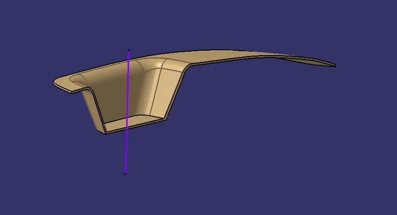
CLASS A SURFACE
CLASS B SURFACE
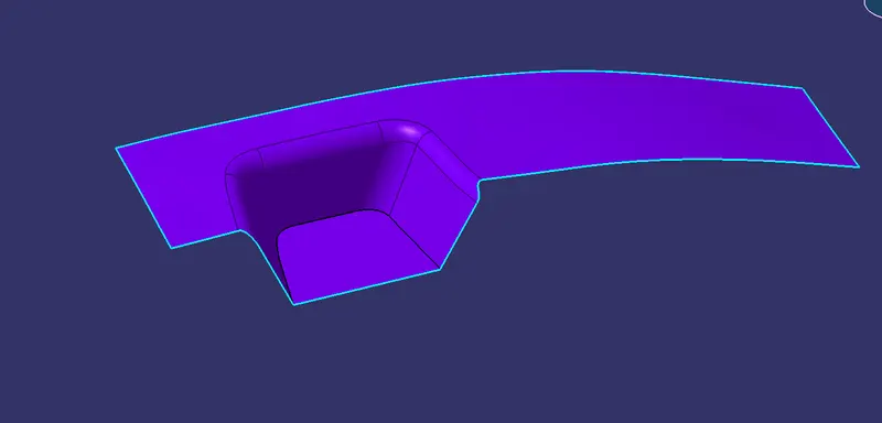
CLASS C SURFACE
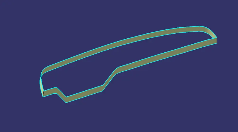
FINAL TRIM STEP
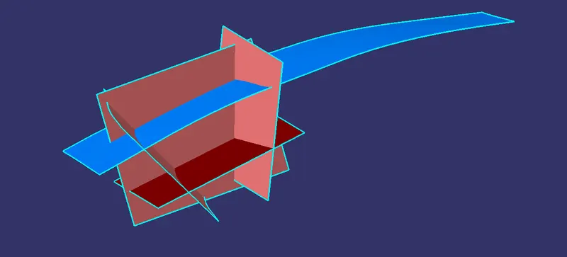
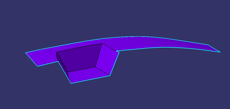
FILLETS
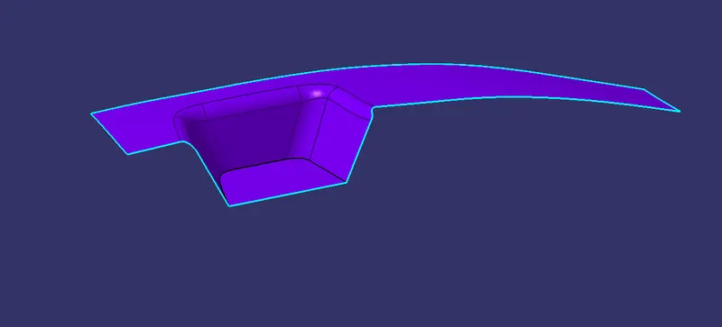
DRAFT ANALYSIS
FRONT VIEW
SIDE VIEW
TOP VIEW
ISOMETRIC VIEW
ALL VIEWS
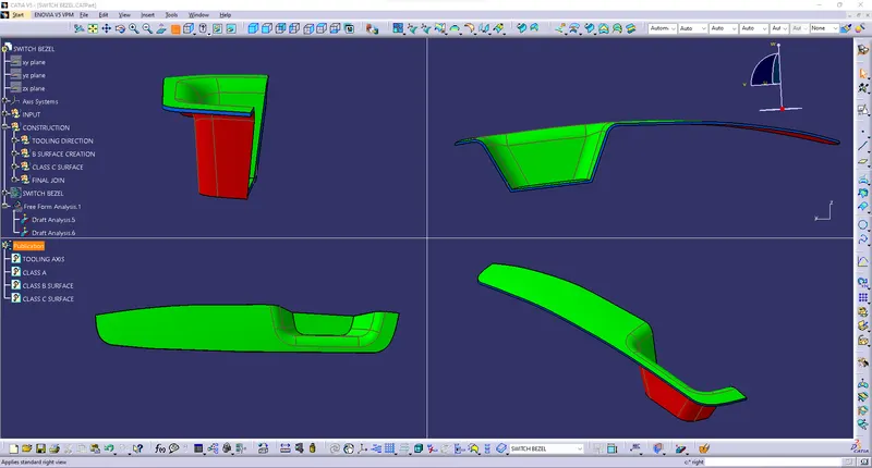
FINAL COMPONENT
FRONT VIEW
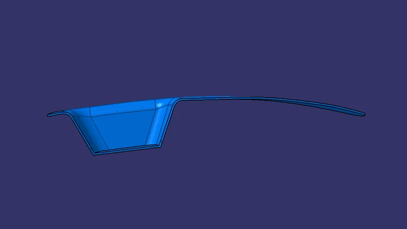
SIDE VIEW
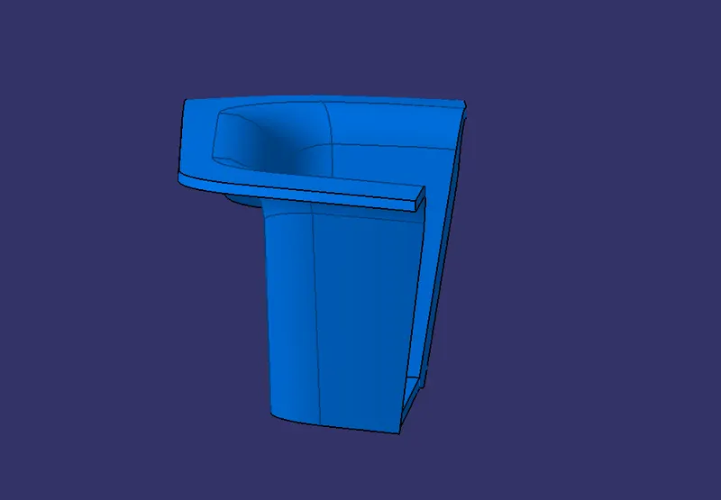
TOP VIEW
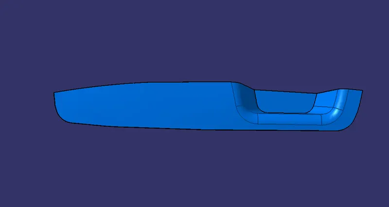
ISOMETRIC VIEW
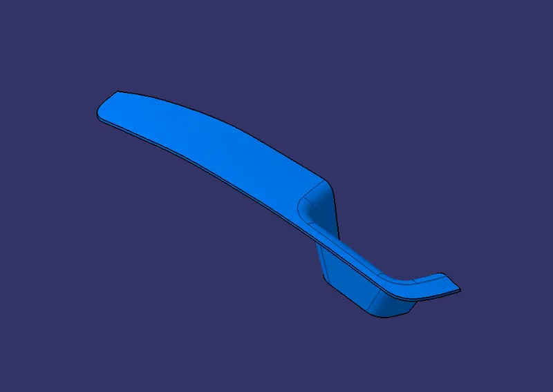
CLOSED SURFACE BODY
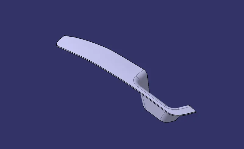
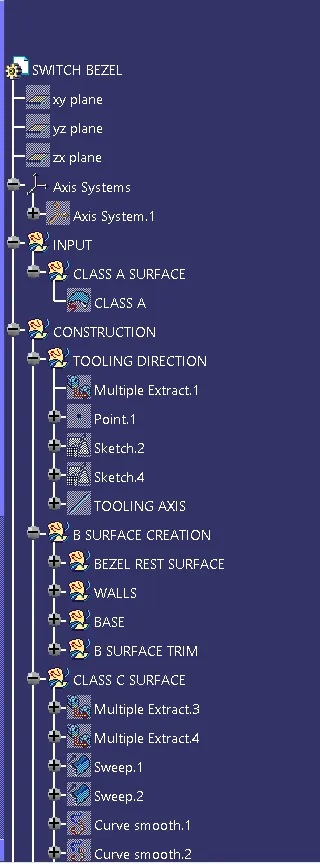
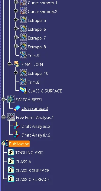
FEATURE TREE