Week 8 - Challenge 2 - Switch Bezel Design
Switch Bezel Design
OBJECTIVE
To Create the switch bazel Plastic component through the given Class-A surface. To begin with, the tooling axis for the given Class-A Surface should be created meeting the requirements of the draft angle and at the end perform the Draft analysis on the model.
INTRODUCTION
Class A surface: It provides information about the aesthetic features of a component. The product designer starts development of design models from class A surface
Class B surface: It provides information about the engineering features of a component. This surface is created by offsetting it from class A surface.
Class C surface: It is a surface that connects surface A and surface B along tooling direction.
Tooling Axis: It is direction along which the core and cavity open and close. Draft is also given along the tooling axis.
DRAFT ANALYSIS OF SURFACE
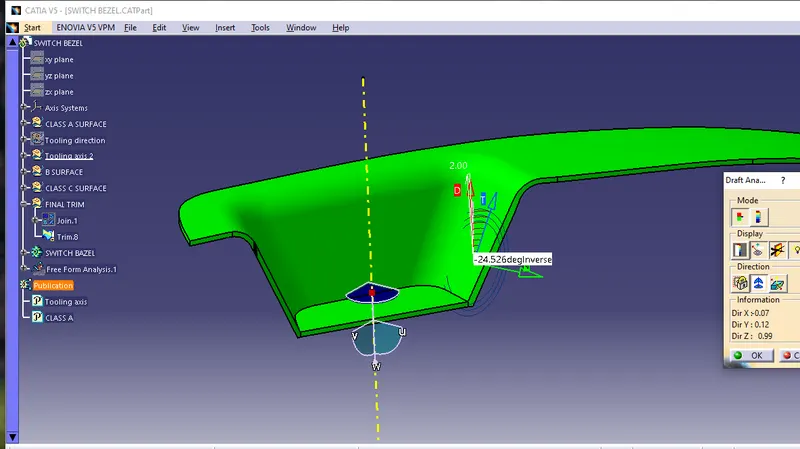
Fig.1.1 Draft analyis of surface
TOOLING AXIS
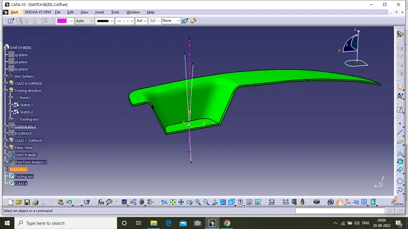
Fig.1.2 Bisecting method
Create tooling axis first i make tooling axis and Create intersect from Class A surface, Now two lines created on angled surface using point-point feature. Now by using Bisecting line the main tooling Axis created.
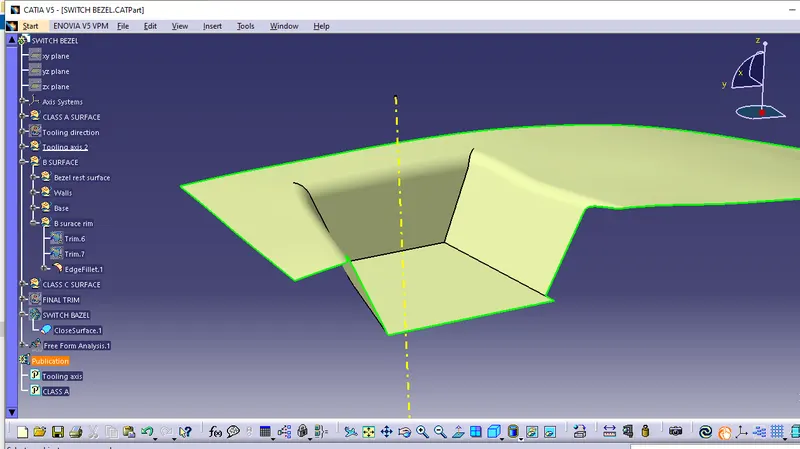
Fig.1.3 Class B surface
Here showing class A surafce and Class b surface.
Class B surface is created from class A surface using extract and offset tool in CATIA V5.
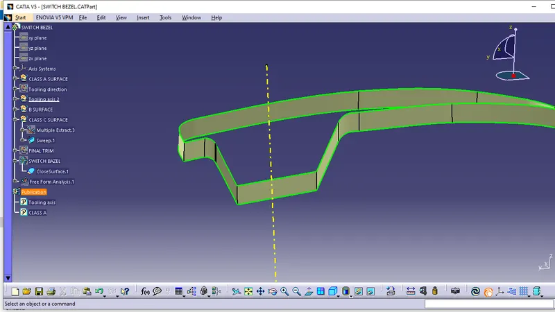
Fig.1.4 Class C surface
Class c surface nothing but. it is thikenning a part.
Here using sweep tool thickened of 2.5 mm.
At last join together Class A,B and C surfaces.
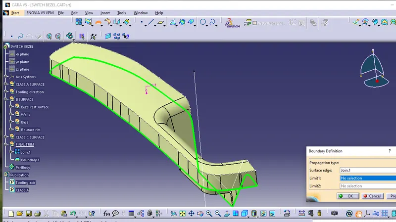
Fig.1.5 Boundary extracting
Here doing boundry extracting for creating sweep from surface A.
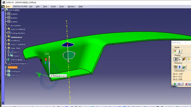
Fig.1.6 Final component
CLOSEST SURFACE
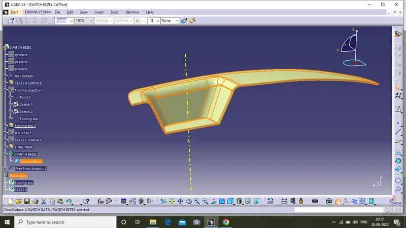
Fig.1.7 Close Surface
At the fininshing of component is close surface using close surface tool in part design work bench.
It is solid part from surface.
RESULT
Here, used two types of tooling axis,
one is bisecting method tooling direction.It is little complicated.Another one is Normal to surface method tooling axis. It is easy method to creating tooling axis.
In the above bisecting method is not working properly.
so used other method simple line it is creating by normal to surface line command.
Conclusion
Created Switch bazel with given parameters.
Here used class A surface as referance.
Tree stucture is maintained.
Tooling axis created by using Normal to surface line command .